
Concept explainers
Videos
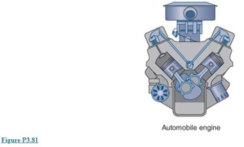
An engine, shown in Fig P3.81, consists of a 100−kg cast iron block with a 20−kg aluminum head, 20kg of steel parts, 5 kg of engine oil, and 6 kg of glycol (antifreeze). All initial temperatures are 5cC, and as the engine starts we want to know the final uniform temperature if it receives 5 kW of heat during 15 min.
Want to see the full answer?
Check out a sample textbook solution
Chapter 3 Solutions
FUNDAMENTALS OF THERMODYNAMICS
Additional Engineering Textbook Solutions
Computer Science: An Overview (13th Edition) (What's New in Computer Science)
Java: An Introduction to Problem Solving and Programming (8th Edition)
Starting Out with Python (4th Edition)
Thinking Like an Engineer: An Active Learning Approach (4th Edition)
Web Development and Design Foundations with HTML5 (8th Edition)
Starting Out with Programming Logic and Design (5th Edition) (What's New in Computer Science)


- can you please help me perform Visual Inspection and Fractography of the attatched image: Preliminary examination to identify the fracture origin, suspected fatigue striation, and corrosion evidences. Do not use Ai.arrow_forwardFor the beam shown, determine: 1) The beam reactions 2) The cutting force and bending moment diagrams including the relevant values. 3) Draw the deformed of the beam (approximate elastic curve). 4) Determine the equation of the charge w(x) 5) Use the fourth-order differential equation: The y'*'* = - w(x) 6) Find the slope and deflection equations (elastic curve) 7) Indicate the slope and deflection values at the free end ( 0в, в)arrow_forwardFor the beam and loads shown, determine the reaction in A and the bending moment equation. Show procedurearrow_forward
- Can you show workings and an explanation for a. and b. Thanksarrow_forward1 F/2 F/2 Collar Nut F/2 1F/2 The figure shows a square thread and nut. The axial load is 1000 lb. The friction coefficients (μ and μ) are 0.15. The collar diameter is 1.75 in. The major diameter is 1.25 in and the pitch is 0.2 in. Answer the following questions. (a) Find the torque required to raise and lower the load. (b) What is the efficiency of the power screw during the lift? (c) Without collar, find if the power screw is self-locked or self- lowered.arrow_forward2 - The figure illustrates the connection of a cylinder head to a pressure vessel using 10 bolts and a confined-gasket scal. The effective sealing diameter is 150 mm. Other dimensions are: A 100, B 200, C300, D = 20, and E = 20, all in millimeters. The cylinder is used to store gas at a static pressure of 6 MPa. ISO class 8.8 bolts with a diameter of 12 mm have been selected. This provides an acceptable bolt spacing. What load factor results from this selection? - B Cylinder head and cylinder is Steel (E=207GPa) (a) Find A and A, when 1 is 30mm. (b) Find k₁ and km (Use α=30°). (c) Determine F₁ for permanent connections. (d) Find the factor of safety for bolts (static loading). (e) When the pressure is cycling between 0 and 8MPa, determine the safety factor (for bolts) using Goodman criterion.arrow_forward
- 3 מון Jin -1 in 600 lbf in in 16 UNC 52 in 2in 3in The figure shows a connection that employs three SAE grade 5 bolts. The members are cold-drawn AISI 1020 steel. On the static load, find the shear loads in the bolt having maximum shear load and find the factor of safety for the bolt. Note: Consider 3 threads after nuts.arrow_forwardPerform the analysis of the following mass-spring system to obtain the differential equation of motion. Include: Static analysis diagrams Dynamic analysis diagrams Complementary system behavior diagramarrow_forwardIn dairy processing piping networks, components such as Y-pieces and T-junctions are often usedto split or combine flows. While these fittings are essential for system functionality, they canintroduce significant resultant forces due to momentum changes, particularly under high flowconditions or through a considerable reduction in the diameter of the pipe. Such forces cancontribute to increased mechanical stresses and potential misalignments. Additionally, thefittings can cause elevated turbulence and localised pressure fluctuations, potentiallyaccelerating wear of pipe surfaces.In this task, milk flows through a double nozzle (Y-piece configuration) as shown in the figure. Thenozzles are open to the atmosphere, and the axes of the pipes and both nozzles lie within thehorizontal plane. The milk exits each nozzle at a velocity of 18 m/s.Tasks• Calculate the magnitude and direction of the resultant force exerted on the doublenozzle assembly.Reflection• Reflect on the assumptions made…arrow_forward
 Refrigeration and Air Conditioning Technology (Mi...Mechanical EngineeringISBN:9781305578296Author:John Tomczyk, Eugene Silberstein, Bill Whitman, Bill JohnsonPublisher:Cengage Learning
 Principles of Heat Transfer (Activate Learning wi...Mechanical EngineeringISBN:9781305387102Author:Kreith, Frank; Manglik, Raj M.Publisher:Cengage Learning
 International Edition---engineering Mechanics: St...Mechanical EngineeringISBN:9781305501607Author:Andrew Pytel And Jaan KiusalaasPublisher:CENGAGE L
 Automotive Technology: A Systems Approach (MindTa...Mechanical EngineeringISBN:9781133612315Author:Jack Erjavec, Rob ThompsonPublisher:Cengage Learning
 Mechanics of Materials (MindTap Course List)Mechanical EngineeringISBN:9781337093347Author:Barry J. Goodno, James M. GerePublisher:Cengage Learning