
MECHANICS OF MATERIALS (LOOSE)-W/ACCESS
10th Edition
ISBN: 9780134583228
Author: HIBBELER
Publisher: PEARSON
expand_more
expand_more
format_list_bulleted
Videos
Textbook Question
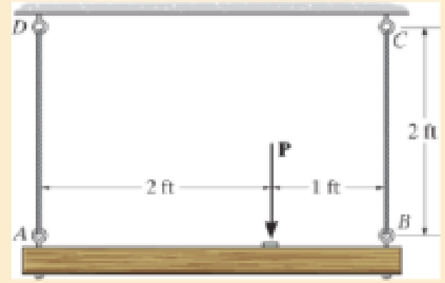
Chapter 3, Problem 3.4RP
The wires each have a diameter of
Expert Solution & Answer

Learn your wayIncludes step-by-step video

schedule05:08
Students have asked these similar questions
The single degree of freedom (SDOF) system that you studied under free vibration in Assignment #3 - Laboratory Component has been subjected to a strong ground motion. The acceleration at the base (excitation) and the acceleration at the roof (response) of the SDOF system was recorded with sampling rate 50 Hz (50 samples per second, or dt= 0.02 seconds). The file ElCentro.txt includes the two columns of acceleration data. The first column lists the acceleration at the base of the SDOF system. The second column lists the acceleration at the roof of the SDOF system. (a) Plot the time histories of the recorded accelerations at the base and at the roof of the SDOF system. (b) Compute the acceleration, velocity and displacement time histories of the roof of the SDOF system subjected to the recorded base acceleration using the Central Difference method. Plot the accel- eration, velocity and displacement time histories. Plot the restoring force, the damping force, and the inertia force time…
The single degree of freedom (SDOF) system that you studied under free vibration in Assignment #3 - Laboratory Component has been subjected to a strong ground motion. The acceleration at the base (excitation) and the acceleration at the roof (response) of the SDOF system was recorded with sampling rate 50 Hz (50 samples per second, or dt= 0.02 seconds). The file ElCentro.txt includes the two columns of acceleration data. The first column lists the acceleration at the base of the SDOF system. The second column lists the acceleration at the roof of the SDOF system. (a) Plot the time histories of the recorded accelerations at the base and at the roof of the SDOF system. (b) Compute the acceleration, velocity and displacement time histories of the roof of the SDOF system subjected to the recorded base acceleration using the Central Difference method. Plot the accel- eration, velocity and displacement time histories. Plot the restoring force, the damping force, and the inertia force time…
A tensile specimen made of hot-rolled AISI 1020 steel is loaded to point corresponding to a strain of 43%.
60
Su = 66 ksi
Stress σ (ksi)
40 B
20
0
0
0
T
H
Sy = 39 ksi
Se = 36 ksi
Hot-rolled 1020 steel
F
10 20 30 40
50 60 70 80 90 100 110 120 130 140 150 160
Strain € (%)
T
1.1 1.2 1.3 1.4 1.5 1.6 1.7 1.8 1.9 2.0 2.1 2.2 2.3 2.4 2.5 2.6
Area ratio R
0.1
0.2
0.3
0.4
0.5
Area reduction A,
What value of strain is applicable to this location?
0.6
Chapter 3 Solutions
MECHANICS OF MATERIALS (LOOSE)-W/ACCESS
Ch. 3.4 - Define a homogeneous material.Ch. 3.4 - Indicate the points on the stress-strain diagram...Ch. 3.4 - Define the modulus of elasticity E.Ch. 3.4 - At room temperature, mild steel is a ductile...Ch. 3.4 - Engineering stress and strain are calculated using...Ch. 3.4 - As the temperature increases the modulus of...Ch. 3.4 - A 100-mm-long rod has a diameter of 15 mm. If an...Ch. 3.4 - A bar has a length of 8 in. and cross-sectional...Ch. 3.4 - A 10-mm-diameter rod has a modulus of elasticity...Ch. 3.4 - The material for the 50-mm-long specimen has the...
Ch. 3.4 - The material for the 50-mm-long specimen has the...Ch. 3.4 - If the elongation of wire BC is 0.2 mm after the...Ch. 3.4 - A tension test was performed on a steel specimen...Ch. 3.4 - Data taken from a stress-strain test for a ceramic...Ch. 3.4 - Data taken from a stress-strain test for a ceramic...Ch. 3.4 - The stress-strain diagram for a steel alloy having...Ch. 3.4 - The stress-strain diagram for a steel alloy having...Ch. 3.4 - The stress-strain diagram for a steel alloy having...Ch. 3.4 - The rigid beam is supported by a pin at C and an...Ch. 3.4 - The rigid beam is supported by a pin at C and an...Ch. 3.4 - Acetal plastic has a stress-strain diagram as...Ch. 3.4 - The stress-strain diagram for an aluminum alloy...Ch. 3.4 - The stress-strain diagram for an aluminum alloy...Ch. 3.4 - The stress-strain diagram for an aluminum alloy...Ch. 3.4 - A bar having a length of 5 in. and cross-sectional...Ch. 3.4 - The rigid pipe is supported by a pin at A and an...Ch. 3.4 - The rigid pipe is supported by a pin at A and an...Ch. 3.4 - Direct tension indicators are sometimes used...Ch. 3.4 - The rigid beam is supported by a pin at C and an...Ch. 3.4 - The rigid beam is supported by a pin at C and an...Ch. 3.4 - The stress-strain diagram for a bone is shown, and...Ch. 3.4 - The stress-strain diagram for a bone is shown and...Ch. 3.4 - The two bars are made of a material that has the...Ch. 3.4 - The two bars are made of a material that has the...Ch. 3.4 - The pole is supported by a pin at C and an A-36...Ch. 3.4 - The bar DA is rigid and is originally held in the...Ch. 3.7 - A 100-mm-long rod has a diameter of 15 mm. If an...Ch. 3.7 - A solid circular rod that is 600 mm long and 20 mm...Ch. 3.7 - A 20-mm-wide block is firmly bonded to rigid...Ch. 3.7 - A 20-mm-wide block is bonded to rigid plates at...Ch. 3.7 - The acrylic plastic rod is 200 mm long and 15 mm...Ch. 3.7 - The plug has a diameter of 30 mm and fits within a...Ch. 3.7 - The elastic portion of the stress-strain diagram...Ch. 3.7 - The elastic portion of the stress-strain diagram...Ch. 3.7 - The brake pads for a bicycle tire are made of...Ch. 3.7 - The lap joint is connected together using a 1.25...Ch. 3.7 - The lap joint is connected together using a 1.25...Ch. 3.7 - The rubber block is subjected to an elongation of...Ch. 3.7 - The shear stress-strain diagram for an alloy is...Ch. 3.7 - A shear spring is made from two blocks of rubber,...Ch. 3 - The elastic portion of the tension stress-strain...Ch. 3 - The elastic portion of the tension stress-strain...Ch. 3 - The rigid beam rests in the horizontal position on...Ch. 3 - The wires each have a diameter of 12 in., length...Ch. 3 - The wires each have a diameter of 12 in., length...Ch. 3 - diameter steel bolts. If the clamping force in...Ch. 3 - The stress-strain diagram for polyethylene, which...Ch. 3 - The pipe with two rigid caps attached to its ends...Ch. 3 - The 8-mm-diameter bolt is made of an aluminum...Ch. 3 - An acetal polymer block is fixed to the rigid...
Additional Engineering Textbook Solutions
Find more solutions based on key concepts
This statement can cause other program statements to execute only under certain conditions. 1. Conditional 2. D...
Starting Out With Visual Basic (8th Edition)
Suppose that you are defining an ADT class and that you then use this class in a program. You want to separate ...
Problem Solving with C++ (10th Edition)
Pennies for Pay Write a program that calculates the amount of money a person would earn over a period of time i...
Starting Out with Python (4th Edition)
What is a default constructor? Is it possible to have more than one default constructor?
Starting Out with C++ from Control Structures to Objects (9th Edition)
Compare and contrast the break and continue statements.
Java How to Program, Early Objects (11th Edition) (Deitel: How to Program)
Distinguish among data definition commands, data manipulation commands, and data control commands.
Modern Database Management
Knowledge Booster


Learn more about
Need a deep-dive on the concept behind this application? Look no further. Learn more about this topic, mechanical-engineering and related others by exploring similar questions and additional content below.Similar questions
- A tensile specimen made of hot-rolled AISI 1020 steel is loaded to point corresponding to a strain of 40%. 60 Su = 66 ksi Stress σ (ksi) S₁ = 39 ksi 40 Se = 36 ksi Hot-rolled 1020 steel 20 0 10 20 30 40 50 60 70 80 90 100 110 120 130 140 150 160 Strain € (%) 0 1.1 1.2 1.3 1.4 1.5 1.6 1.7 1.8 1.9 2.0 2.1 2.2 2.3 2.4 2.5 2.6 Area ratio R 0.1 0.2 0.3 0.4 0.5 Area reduction A, What value of area ratio is applicable to this location? 0.6arrow_forwardA tensile specimen made of hot-rolled AISI 1020 steel is loaded to point corresponding to a strain of 43%. 60 Su = 66 ksi Stress σ (ksi) 20 Sy = 39 ksi Se = 36 ksi Hot-rolled 1020 steel F 0 10 20 30 40 50 60 70 80 90 100 110 120 130 140 150 160 Strain € (%) 0 1.1 1.2 1.3 1.4 1.5 1.6 1.7 1.8 1.9 2.0 2.1 2.2 2.3 2.4 2.5 2.6 Area ratio R 0.1 0.2 0.3 0.4 0.5 Area reduction A, What value of area reduction is applicable to this location? 0.6arrow_forwardTable of Measurements and Results: Reading m/s Ji- a (wh Nu h Re Nu Error% (C) (°C) 2 1 Discussion: 1-Estimate the heat transfer and experimental value of the heat transfer coefficient hex with its unit and Nusselt number Nu expl 2- Find the percentage error for the value of the experimental Nusselt number. 3-Draw the graph showing a relationship between the temperatures difference (T-T) and theoretical and experimental value of Nusselt number. 4-The forced convection heat transfer coefficient of a plate depends on which of the following: a-gravity. b-velocity of fluid. e-conductivity of fluid. d-conductivity of plate material. Experiment: Internal Forced convenction Heat trovate on now through t objectives. Study the convection heat transfer of air flow through stage Calculations. Q & (T-T) Vary Re Q. heup A (TT) (T. Te-T ASPL Nep Re 117 RITT 14 ' 14arrow_forward
- If AE = 1.6 m, ED = CD = 1.9 m and F = 3.1 kN, then find the magnitude of the force acting in EB. B 30° 30° C E D ED m DC m ♥F KNarrow_forwardAssume multiple single degree of freedom systems with natural periods T ∈ [0.05, 2.00] seconds with in- crement of period dT = 0.05 seconds. Assume three cases of damping ratio: Case (A) ξ = 0%; Case (B) ξ = 2%; Case (C) ξ = 5%. The systems are initially at rest. Thus, the initial conditions are u(t = 0) = 0 and ̇u(t = 0) = 0. The systems are subjected to the base acceleration that was provided in the ElCentro.txt file (i.e., first column). For the systems in Case (A), Case (B), and Case (C) and for each natural period compute the peak acceleration, peak velocity, and peak displacement responses to the given base excitation. Please, use the Newmark method for β = 1/4 (average acceleration) to compute the responses. Create three plots with three lines in each plot. The first plot will have the peak accelerations in y-axis and the natural period of the system in x-axis. The second plot will have the peak velocities in y-axis and the natural period of the system in x-axis. The third plot…arrow_forwardDetermine the resultant stress at points P and Q.arrow_forward
- For the notched specimen with h = 0.13 m and r =11 mm, calculate the nominal stress for F=5 kN. F h F 25 mm Please submit your answer in the units of MPa.arrow_forwardA tensile specimen made of hot-rolled AISI 1020 steel is loaded to point corresponding to a strain of 49%. 60 Su = 66 ksi Stress σ (ksi) Sy = 39 ksi 400B Se = 36 ksi Hot-rolled 1020 steel 20 F 0 0 10 20 30 40 50 60 70 80 90 100 110 120 130 140 150 160 Strain € (%) 0 1.1 1.2 1.3 1.4 1.5 1.6 1.7 1.8 1.9 2.0 2.1 2.2 2.3 2.4 2.5 2.6 Area ratio R 0.1 0.2 0.3 0.4 0.5 Area reduction A, What value of Su is applicable to this location? 0.6arrow_forwardA tensile specimen made of hot-rolled AISI 1020 steel is loaded to point corresponding to a strain of 40%. 60 Su = 66 ksi Stress σ (ksi) 40 20 Sy= = 39 ksi Se = 36 ksi Hot-rolled 1020 steel F | G | H 0 10 20 30 40 50 60 0 70 80 90 100 110 120 130 140 150 160 Strain € (%) ☐ T 1.1 1.2 1.3 1.4 1.5 1.6 1.7 1.8 1.9 2.0 2.1 2.2 2.3 2.4 2.5 2.6 Area ratio R 0.1 0.2 0.3 0.4 0.5 Area reduction A, What value of Sy is applicable to this location? 0.6arrow_forward
- A vertical .2m by .2m square plate is exposed to saturated water vapor at atmospheric pressure. If the surface temperature is 80 degrees C and the flow is laminar, estimate the loal heat transfer coefficents at the middles and at the bottom of the plate.arrow_forwardA transformer that is 10 cm long, 6.2 cm wide, and 5 cm high is to be cooled by attaching a 10 cm by 6.2 cm wide polished aluminum heat sink(emissivity=.03) to its top surface. The heat sink has seven fins, which are 5 mm high, 2mm thick, and 10 cm long. A fan blows air at 25 degrees C parallel to the passages between the fins. The heat sink is to dissipate 12W of heat, and the base temp of the ehat sink is not to exceed 60 degrees C. Assuming the fins and the base plate to be nearly isothermal and the radiation heat transfer to be negligible, determine the minimum free-stream velocity the fan needs to supply to avoid overheating. Assume the flow is laminar over the entire finned surface of the transformer.arrow_forwardI need a mechanical engineering expert to solve this question,no Ai pleasearrow_forward
arrow_back_ios
SEE MORE QUESTIONS
arrow_forward_ios
Recommended textbooks for you
 International Edition---engineering Mechanics: St...Mechanical EngineeringISBN:9781305501607Author:Andrew Pytel And Jaan KiusalaasPublisher:CENGAGE L
International Edition---engineering Mechanics: St...
Mechanical Engineering
ISBN:9781305501607
Author:Andrew Pytel And Jaan Kiusalaas
Publisher:CENGAGE L
How to balance a see saw using moments example problem; Author: Engineer4Free;https://www.youtube.com/watch?v=d7tX37j-iHU;License: Standard Youtube License