
Concept explainers
Videos
What is the principal difference between a synchronous machine and an induction machine?
To discuss: The principal difference between a synchronous machine and an induction machine.
Explanation of Solution
The principal difference between the synchronous machine and the induction machine are as follows:
Constructional difference:
The stator of both the machines are similar in construction except the rotor and the slip ring arrangement.The rotor of the synchronous machine has either salient pole or cylindrical poleconstruction.Among these two, the salient pole rotor is most common. The windings of the rotor are provided with dc supply with the help of the slip rings. The cylindrical rotor of the synchronous motor is shown below.

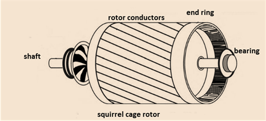
The rotor of the induction motor has either squirrel cage or wound rotor type construction. In squirrel cage induction motor the conductors are shorted with the help of the end ring. While in the wound rotor the windings are permanently shorted. The squirrel cage rotor of the induction motor is shown below.
Difference in the working principle:
Synchronous machine: The synchronous machine always runs at the synchronous speed.
The synchronous speed of the Synchronous machine is given by then equation:
Induction machine:
The relative difference between the speed of the stator and the rotor m.m.f causes the induction machine to rotate.
Induction machine always runs at the speed which is lower than synchronous speed.
Want to see more full solutions like this?
Chapter 3 Solutions
Electric machinery fundamentals


- Find the valve of V using the Thevenin Equivalent Circuit and then determine if the 8 ohm resistor allows maximum power transfer. If not, then what value should the 8 ohm resistor be changed to for maximum power transfer? ZA 6 6 + 22V 83 V 34 2 6 АААА ААААarrow_forwardFind the valve of voltage Vx using the THE VIN IN equivalent circuit ww 8 Show the Theven in Circuit. I 7V ZV m 6 5 M + 4 34 АА 3 1 АААА 9A ↑ 24arrow_forwardDon't use ai to answer I will report you answerarrow_forward
- A speech signal has frequencies in the range 50- 3500 Hz. The signal is sampled at Nyquist sampling rate and the resulting pulses are transmitted over PAM and PCM systems. 1- Calculate the minimum bandwidth of the PAM system. 2- Calculate the minimum bandwidth of the PCM system, when the pulses are quantized into 121 levels B) Draw the signaling waveform (line codes) for the binary sequence 10110001 using (Unipolar NRZ, Bipolar RZ, Bipolar NRZ, Manchester code, Differential Manchester (split phase).arrow_forwardDon't use ai to answer I will report you answerarrow_forwardDon't use ai to answer I will report you answerarrow_forward
 Delmar's Standard Textbook Of ElectricityElectrical EngineeringISBN:9781337900348Author:Stephen L. HermanPublisher:Cengage Learning