
Concept explainers
Videos
Define the following examples as path, motion, or function generation cases.
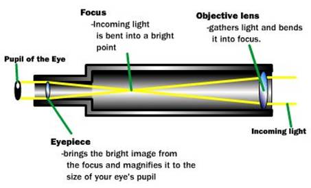
- A telescope aiming (star tracking)
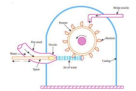
mechanism - A backhoe bucket control mechanism
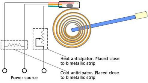
- A thermostat adjusting mechanism
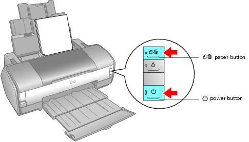
- A computer printer head moving mechanism
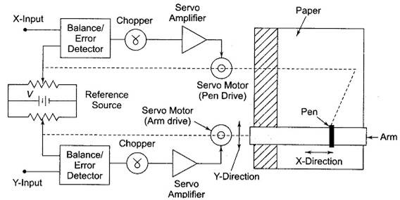
- An XY plotter pen control mechanism
a.
To define:The following examples of telescope aimingcases study given in the problem.
Explanation of Solution
Given information:
The case study of the initial conditions is given that about a telescope aiming or star tracking mechanism.
Calculation:
A telescope aiming or star tracking mechanism that shows a path generation. A star goes along the sky with a
The working mechanism in the line diagram is shown below.
b.
To define: The following examples bucket control arrangement case study given in the problem.
Explanation of Solution
Given information:
The case study of the initial conditions is given that about a telescope aiming or star tracking mechanism.
Calculation:
This is motion generation mainly todigging a trench, say; the location and bucket alignment must becontrolled.
The working mechanism in the line diagram is shown below.
c.
To Define:The following example of thermostat adjusting mechanism case study given in the problem.
Explanation of Solution
This thermostat adjusting mechanism shows a Function generation.Here the output is a chosen function of input over input range.
The working mechanism in the line diagram is shown below.
d.
ToDefine:The following example of the computer printing head moving mechanism case study given in the problem.
Explanation of Solution
Here a moving mechanism of a computer printing head shows path generation and head to be point on a path.
The working mechanism in the line diagram is shown below.
e.
To find:The following examplesof XY plotter pen control mechanism cases study given in the problem.
Explanation of Solution
Here a control mechanism that having an xy plotter pen shows a Path generation and here a pen goes a straight line from point to point.
The working mechanism in the line diagram is shown below.
Want to see more full solutions like this?
Chapter 3 Solutions
DESIGN OF MACHINERY (LL+CONNECT)


- CORRECT AND DETAILED SOLUTION WITH FBD ONLY. I WILL UPVOTE THANK YOU. CORRECT ANSWER IS ALREADY PROVIDED. I REALLY NEED FBD. The roof truss shown carries roof loads, where P = 10 kN. The truss is consisting of circular arcs top andbottom chords with radii R + h and R, respectively.Given: h = 1.2 m, R = 10 m, s = 2 m.Allowable member stresses:Tension = 250 MPaCompression = 180 MPa1. If member KL has square section, determine the minimum dimension (mm).2. If member KL has circular section, determine the minimum diameter (mm).3. If member GH has circular section, determine the minimum diameter (mm).ANSWERS: (1) 31.73 mm; (2) 35.81 mm; (3) 18.49 mmarrow_forwardPROBLEM 3.23 3.23 Under normal operating condi- tions a motor exerts a torque of magnitude TF at F. The shafts are made of a steel for which the allowable shearing stress is 82 MPa and have diameters of dCDE=24 mm and dFGH = 20 mm. Knowing that rp = 165 mm and rg114 mm, deter- mine the largest torque TF which may be exerted at F. TF F rG- rp B CH TE Earrow_forward1. (16%) (a) If a ductile material fails under pure torsion, please explain the failure mode and describe the observed plane of failure. (b) Suppose a prismatic beam is subjected to equal and opposite couples as shown in Fig. 1. Please sketch the deformation and the stress distribution of the cross section. M M Fig. 1 (c) Describe the definition of the neutral axis. (d) Describe the definition of the modular ratio.arrow_forward
- using the theorem of three moments, find all the moments, I only need concise calculations with minimal explanations. The correct answers are provided at the bottomarrow_forwardMechanics of materialsarrow_forwardusing the theorem of three moments, find all the moments, I need concise calculations onlyarrow_forward
- Can you provide steps and an explaination on how the height value to calculate the Pressure at point B is (-5-3.5) and the solution is 86.4kPa.arrow_forwardPROBLEM 3.46 The solid cylindrical rod BC of length L = 600 mm is attached to the rigid lever AB of length a = 380 mm and to the support at C. When a 500 N force P is applied at A, design specifications require that the displacement of A not exceed 25 mm when a 500 N force P is applied at A For the material indicated determine the required diameter of the rod. Aluminium: Tall = 65 MPa, G = 27 GPa. Aarrow_forwardFind the equivalent mass of the rocker arm assembly with respect to the x coordinate. k₁ mi m2 k₁arrow_forward
 Understanding Motor ControlsMechanical EngineeringISBN:9781337798686Author:Stephen L. HermanPublisher:Delmar Cengage Learning