
Concept explainers
Videos
Define the following examples as path, motion, or function generation cases.
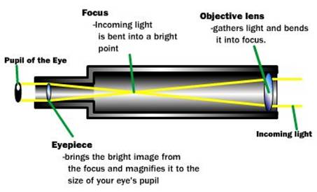
- A telescope aiming (star tracking)
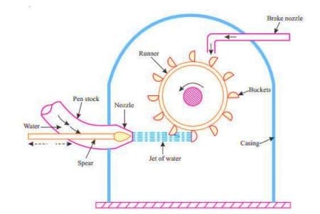
mechanism - A backhoe bucket control mechanism
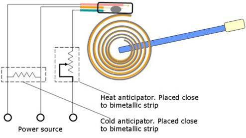
- A thermostat adjusting mechanism
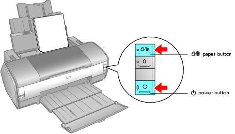
- A computer printer head moving mechanism
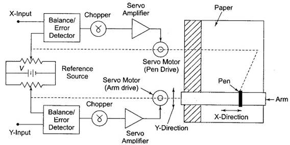
- An XY plotter pen control mechanism
a.
To define:The following examples of telescope aimingcases study given in the problem.
Explanation of Solution
Given information:
The case study of the initial conditions is given that about a telescope aiming or star tracking mechanism.
Calculation:
A telescope aiming or star tracking mechanism that shows a path generation. A star goes along the sky with a
The working mechanism in the line diagram is shown below.
b.
To define: The following examples bucket control arrangement case study given in the problem.
Explanation of Solution
Given information:
The case study of the initial conditions is given that about a telescope aiming or star tracking mechanism.
Calculation:
This is motion generation mainly todigging a trench, say; the location and bucket alignment must becontrolled.
The working mechanism in the line diagram is shown below.
c.
To Define:The following example of thermostat adjusting mechanism case study given in the problem.
Explanation of Solution
This thermostat adjusting mechanism shows a Function generation.Here the output is a chosen function of input over input range.
The working mechanism in the line diagram is shown below.
d.
ToDefine:The following example of the computer printing head moving mechanism case study given in the problem.
Explanation of Solution
Here a moving mechanism of a computer printing head shows path generation and head to be point on a path.
The working mechanism in the line diagram is shown below.
e.
To find:The following examplesof XY plotter pen control mechanism cases study given in the problem.
Explanation of Solution
Here a control mechanism that having an xy plotter pen shows a Path generation and here a pen goes a straight line from point to point.
The working mechanism in the line diagram is shown below.
Want to see more full solutions like this?
Chapter 3 Solutions
DESIGN OF MACHINERY


- hand-written solutions only please!arrow_forwardA prototype automobile is designed to travel at 65 km/hr. A model of this design is tested in a wind tunnel with identical standard sea- level air properties at a 1:5 scale. The measured model drag is 529 N, enforcing dynamic similarity. Determine (a) the drag force on the prototype and (b) the power required to overcome this drag. See the equation Vm m = D V Dm (a) Dp = i (b) Pp = i N hparrow_forwardA new blimp will move at 6 m/s in 20°C air, and we want to predict the drag force. Using a 1: 14-scale model in water at 20°C and measuring a 2500-N drag force on the model, determine (a) the required water velocity, (b) the drag on the prototype blimp and, (c) the power that will be required to propel it through the air. (a) Vm = i (b) Dp = i (c) Pp = i m/s N Warrow_forward
- Drag measurements were taken for a sphere, with a diameter of 5 cm, moving at 3.7 m/s in water at 20°C. The resulting drag on the sphere was 10 N. For a balloon with 1-m diameter rising in air with standard temperature and pressure, determine (a) the velocity if Reynolds number similarity is enforced and (b) the drag force if the drag coefficient in the equation below is the dependent pi term. li ε pVI D 1 = CD = Q μ (a) Vp = i (b) Dp = i m/s Narrow_forwardCalculate the forces in all members of the truss shown using either the method of joints or the method of sectionsarrow_forward20-4-2025 Exam-2-Tribology Q1: What are the assumptions of hydrodynamic lubrication theory: Q2: Explain with sketch the cycle or process of engine lubrication system-pressurized lubrication system Q3: A short bearing is designed to operate with an eccentricity ratio = 0. 7. The journal diameter is 60 mm, and its speed is 1300 r.p.m. The journal is supported by a short hydrodynamic bearing of length L/D = 0. 5, and clearance ratio C/R = 103. The radial load on the bearing is 9800 N. a. Find the Sommerfeld number. b. Find the minimum viscosity of the lubricant for operating at ε = 0.7 c. Select a lubricant if the average bearing operating temperature is 70°c Q4: Two parallel circular disks of 100 mm diameter have a clearance of Imm between them. Under load, the downward velocity of the upper disk is 2 m/s. At the same time, the lower disk is stationary. The clearance is full of SAE 40 oil at a temperature of 60°c. a. Find the load on the upper disk that results in the instantaneous…arrow_forward
- Tribobolgy 15/2022 Monthly Exam. Automobile Eng. Dert 2nd Semster/3rd class Max. Mark: 100% 7. Viscosity of multi-grade oils (a) Reduces with temperature (c) is less sensitive to temperature (b) Increases with temperature (d) None of the above 8. In a hydrodynamic journal bearing if eccentricity ratio = 1, it means (a) Journal/shaft is subjected to no load and the rotational speed is very high. (b) Journal is subjected to no load and the rotational speed is moderate (c) Journal is subjected to very light load and the rotational speed is very high. (d) Journal is subjected to very high load and the rotational speed is negligible. Q4/ The journal speed of a 100mm diameter journal is 2500 rpm. The journal is supported by a short hydrodynamic bearing of length L=0.6D, eccentricity ratio = 0.75 and a clearance ratio C/R=0.001. The radial load on the bearing is 10 kN. The lubricant is SAE 30, and the operating temperature of the lubricant in the bearing is 700C. 1- Assume…arrow_forward1 of 2 Monthly Exam. Automobile Eng. Dert 2nd Semster/3rd class Max. Mark: 100% Q1/A/ Compare between the long and short journal bearings B/ With the help of Stribeck's curve, discuss different regimes of lubrication. C/ Explain the importance of Tribology in the design of different machine elements Q2 /A/ According to the SAE viscosity grading system all engine oils are divided into two classes: monograde and multi-grade. Compare between them? B/What are the differences between grease and Synthetic oils C/ Explain the effect of eccentricity ratio & with respect to hydrodynamic journal bearing. Q3/A/ What are the major factors which affect the selection of lubricants? B/What are the criteria to classify sliding bearings? C/ Answer of the following: 1. According to the SAE viscosity classification, the oil (SAE 40) is lower viscosity than the oil (SAE 20) at the same temperature. (True or False) 2. For a slow speed-highly loaded bearing, used oils of high viscosity; while for high-speed…arrow_forwardThe uniform rods have a mass per unit length of 10kg/m . (Figure 1)If the dashpot has a damping coefficient of c=50N⋅s/m , and the spring has a stiffness of k=600N/m , show that the system is underdamped, and then find the pendulum's period of oscillation.arrow_forward
- 10-50. The principal plane stresses and associated strains in a plane at a point are σ₁ = 30 ksi, σ₂ = -10 ksi, e₁ = 1.14(10-3), €2=-0.655(103). Determine the modulus of elasticity and Poisson's ratio. emps to plum... Wednesday FI a וח 2 Q Search 48 F5 - F6 4+ F7 FB F9 FIO FII F12 & * S 6 7 8 9 ㅁ F2 # *F3 3 $ 4 F4 % W E R T Y ப S ALT D F G H X C V B N J Σ H L ว { P [ ] ALT " DELETE BACKSPACE NUM LOCK T 7 HOME ENTER 4 PAUSE SHIFT CTRL Earrow_forward10−9. The state of strain at the point has components of ϵx = −100(10−6), ϵy = −200(10−6), and γxy=100(10−6). Use the strain transformation equations to determine (a) the in-plane principal strains and (b) the maximum in-plane shear strain and average normal strain. In each case specify the orientation of the element and show how the strains deform the element within the x−y plane.arrow_forwardThe strain gage is placed on the surface of the steel boiler as shown. If it is 0.5 in. long, determine the pressure in the boiler when the gage elongates 0.2(10−3) in. The boiler has a thickness of 0.5 in. and inner diameter of 60 in. Also, determine the maximum x, y in-plane shear strain in the material. Take Est=29(103)ksi, vst=0.3.arrow_forward
 Understanding Motor ControlsMechanical EngineeringISBN:9781337798686Author:Stephen L. HermanPublisher:Delmar Cengage Learning