
Concept explainers
Videos
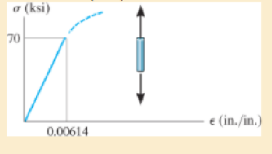
The elastic portion of the tension stress-strain diagram for an aluminum alloy is shown in the figure. The specimen used for the test has a gage length of 2 in. and a diameter of 0.5 in. When the applied load is 9 kip, the new diameter of the specimen is 0.49935 in. Calculate the shear modulus Gal for the aluminum.
The shear modulus for an aluminum alloy
Answer to Problem 1RP
The shear modulus for an aluminum alloy is
Explanation of Solution
Given information:
Gage length is
The diameter of the specimen is
The axial load acts on the specimen is
The new diameter of the specimen is
Calculation:
Calculate the modulus of elasticity for aluminum
Here, the stress is
Refer the stress-strain diagram.
The value of stress is 70 ksi and the value of strain is
Substitute 70 ksi for
The expression to find the cross-sectional area of the specimen
Here, the diameter of the specimen is
Substitute
Find the value of stress when the specimen is loaded with a 9 kip load using the relation:
Here, the load is P.
Substitute 9 kip for P and
The expression to find the strain in the longitudinal or axial direction
Here, the Young’s modulus of the aluminum is
Substitute
Find the strain in lateral direction
Here, the new diameter is
Substitute
Find the Poisson’s ratio
Substitute
Calculate the modulus of rigidity for the specimen
Substitute
Therefore, the shear modulus for an aluminum alloy is
Want to see more full solutions like this?
Chapter 3 Solutions
STANDALONE CODE MECHANICS OF MATERIALS-M
Additional Engineering Textbook Solutions
Starting Out with Programming Logic and Design (5th Edition) (What's New in Computer Science)
Degarmo's Materials And Processes In Manufacturing
Database Concepts (8th Edition)
Java How to Program, Early Objects (11th Edition) (Deitel: How to Program)
Thinking Like an Engineer: An Active Learning Approach (4th Edition)
Computer Science: An Overview (13th Edition) (What's New in Computer Science)


- PROBLEM 3.46 The solid cylindrical rod BC of length L = 600 mm is attached to the rigid lever AB of length a = 380 mm and to the support at C. When a 500 N force P is applied at A, design specifications require that the displacement of A not exceed 25 mm when a 500 N force P is applied at A For the material indicated determine the required diameter of the rod. Aluminium: Tall = 65 MPa, G = 27 GPa. Aarrow_forwardFind the equivalent mass of the rocker arm assembly with respect to the x coordinate. k₁ mi m2 k₁arrow_forward2. Figure below shows a U-tube manometer open at both ends and containing a column of liquid mercury of length l and specific weight y. Considering a small displacement x of the manometer meniscus from its equilibrium position (or datum), determine the equivalent spring constant associated with the restoring force. Datum Area, Aarrow_forward
- 1. The consequences of a head-on collision of two automobiles can be studied by considering the impact of the automobile on a barrier, as shown in figure below. Construct a mathematical model (i.e., draw the diagram) by considering the masses of the automobile body, engine, transmission, and suspension and the elasticity of the bumpers, radiator, sheet metal body, driveline, and engine mounts.arrow_forward3.) 15.40 – Collar B moves up at constant velocity vB = 1.5 m/s. Rod AB has length = 1.2 m. The incline is at angle = 25°. Compute an expression for the angular velocity of rod AB, ė and the velocity of end A of the rod (✓✓) as a function of v₂,1,0,0. Then compute numerical answers for ȧ & y_ with 0 = 50°.arrow_forward2.) 15.12 The assembly shown consists of the straight rod ABC which passes through and is welded to the grectangular plate DEFH. The assembly rotates about the axis AC with a constant angular velocity of 9 rad/s. Knowing that the motion when viewed from C is counterclockwise, determine the velocity and acceleration of corner F.arrow_forward
 Mechanics of Materials (MindTap Course List)Mechanical EngineeringISBN:9781337093347Author:Barry J. Goodno, James M. GerePublisher:Cengage Learning