
(a)
Show that the given circuit satisfies Kirchhoff’s current law at junction terminals x-y.
(a)
Answer to Problem 1P
Yes, the given circuit satisfies Kirchhoff’s current law at junction terminals x-y.
Explanation of Solution
Given data:
Refer to Figure given in the textbook.
The voltage delivered by the source is
PSPICE Simulation:
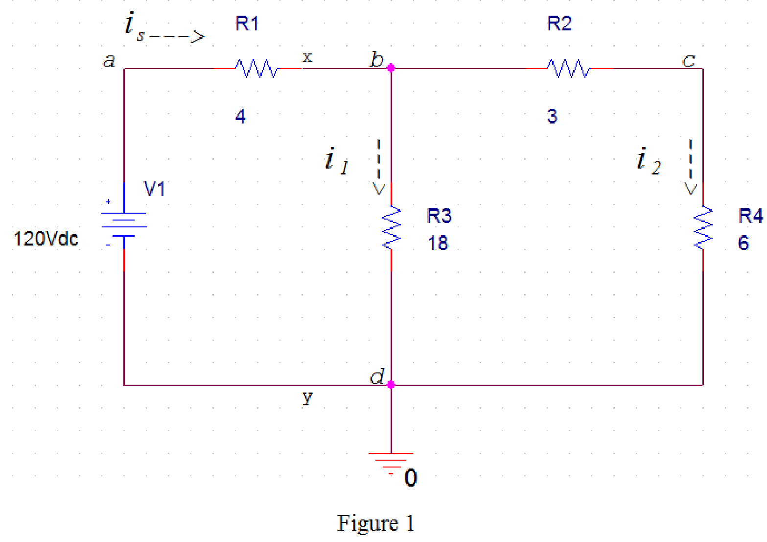
Draw the circuit diagram in PSpice as shown in Figure 1.
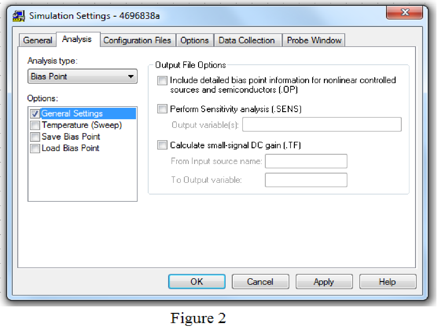
Save the circuit and provide the Simulation Settings as shown in Figure 2.
Now run the simulation and the results will be displayed as shown in Figure 3 by enabling the “Enable Bias Current Display” icon.
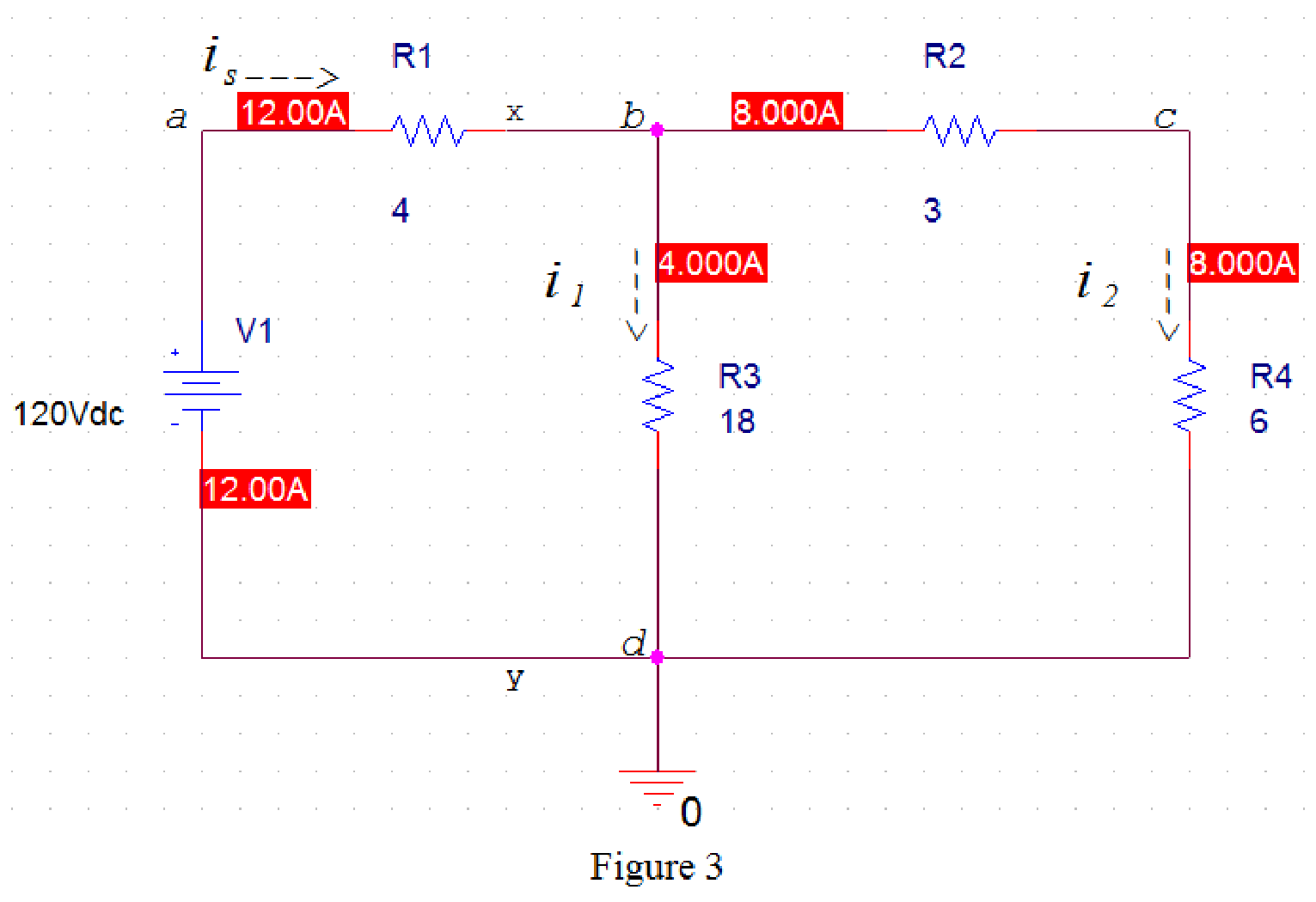
From Figure 3, source current
Kirchhoff’s current law states that the current entering the node is equal to the current leaving the node.
In Figure 3, apply Kirchhoff current law at node b. Therefore,
Rearrange the equation (1) as follows,
Substitute
Hence, the given circuit satisfies Kirchhoff’s current law at junction terminals x-y.
Conclusion:
Thus, yes, the given circuit satisfies Kirchhoff’s current law at junction terminals x-y.
(b)
Show that the given circuit satisfies Kirchhoff’s voltage law.
(b)
Answer to Problem 1P
Yes, the given circuit satisfies Kirchhoff’s voltage law.
Explanation of Solution
Given data:
Refer to Figure given in the textbook.
Voltage delivered by the source is
PSPICE Simulation:
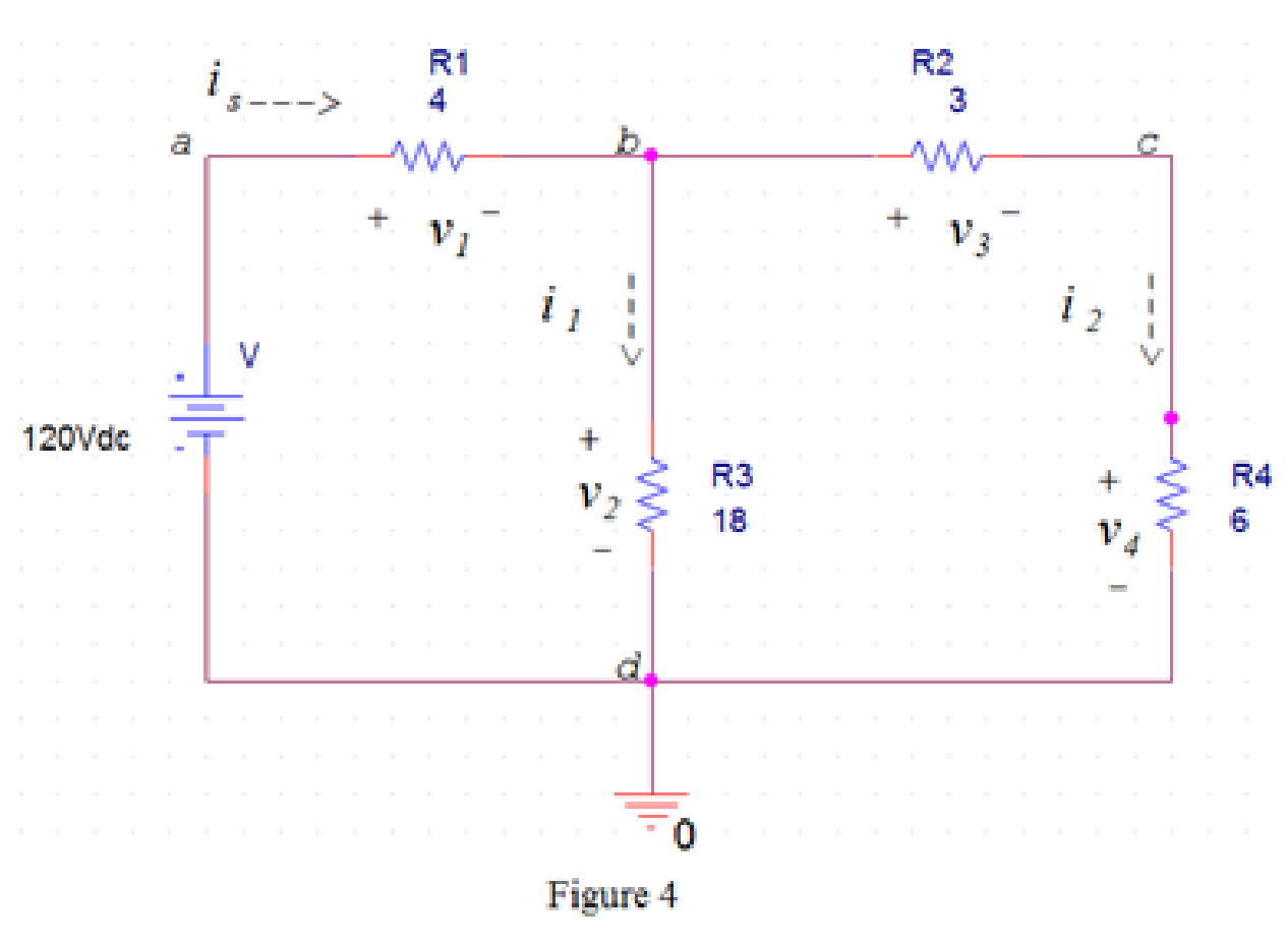
Draw the circuit diagram in PSpice as shown in Figure 4.
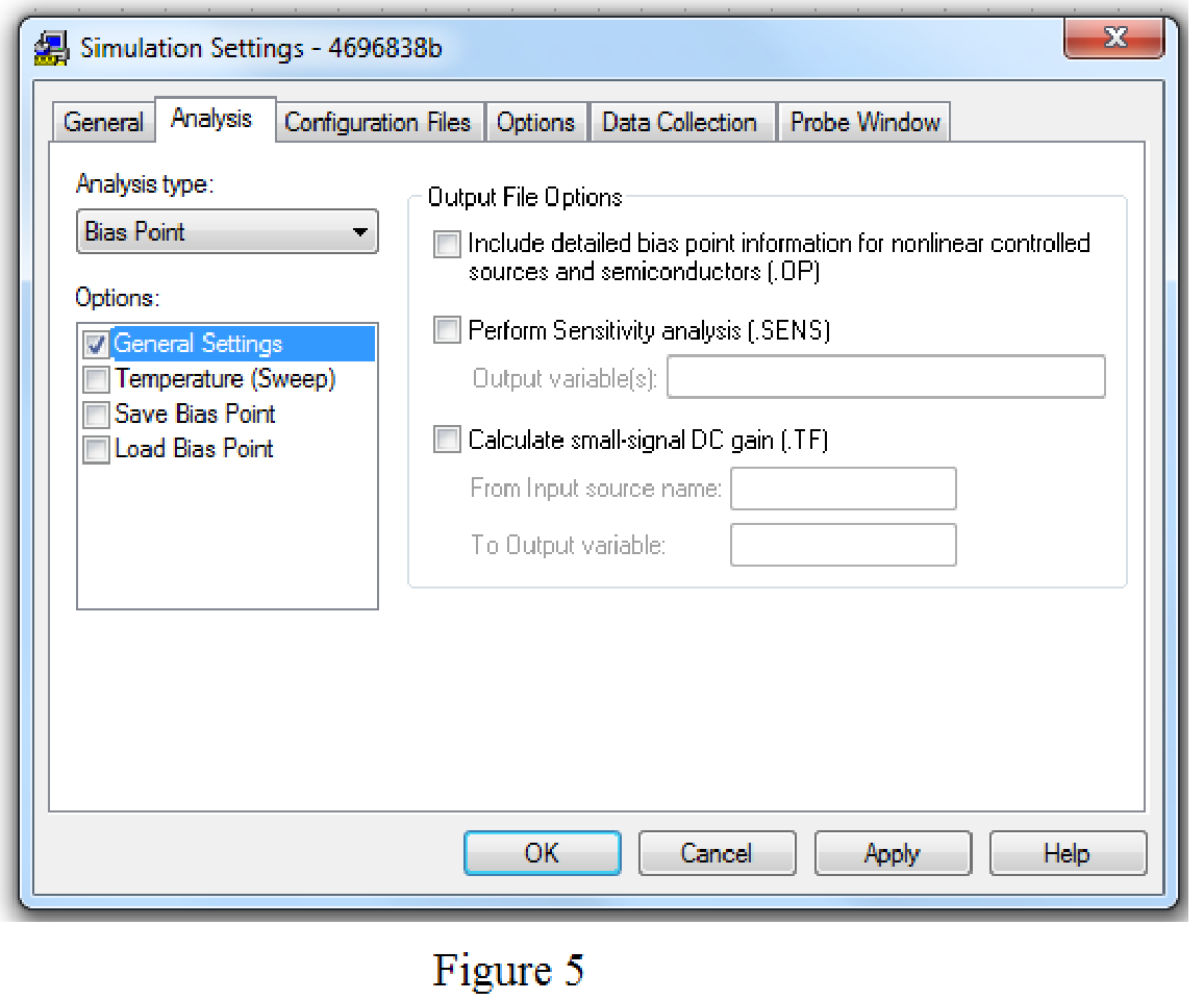
Save the circuit and provide the Simulation Settings as shown in Figure 5.
Now run the simulation and the results will be displayed as shown in Figure 3 by enabling the “Enable Bias Current Display” icon and “Enable Bias Voltage Display” icon.
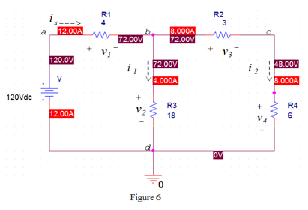
From Figure 6, the voltage
The voltage
The voltage
The voltage
Kirchhoff’s voltage law states that the sum of the voltage rise around any closed loop must be equal to the sum of voltage drops around that loop.
In Figure 6, apply Kirchhoff’s voltage law to the loop abda.
From Figure 6, the source voltage
Substitute
In Figure 6, apply Kirchhoff’s voltage law to the loop bcdb.
Substitute
In Figure 6, apply Kirchhoff’s voltage law to the loop abcda.
Substitute
Hence, the given circuit satisfies Kirchhoff’s voltage law around every closed loop.
Conclusion:
Thus, yes, the given circuit satisfies Kirchhoff’s voltage law.
Want to see more full solutions like this?
Chapter 3 Solutions
EBK ELECTRIC CIRCUITS

- 10.8 In the network of Fig. P10.8, Za = Zb = Zc = (25+ j5) W.Determine the line currents.arrow_forwardUsing D flip-flops, design a synchronous counter. The counter counts in the sequence 1,3,5,7, 1,7,5,3,1,3,5,7,.... when its enable input x is equal to 1; otherwise, the counter count 0. Present state Next state x=0 Next state x=1 Output SO 52 S1 1 S1 54 53 3 52 53 S2 56 51 0 $5 5 54 S4 53 0 55 58 57 7 56 56 55 0 57 S10 59 1 58 58 S7 0 59 S12 S11 7 $10 $10 59 0 $11 $14 $13 5 $12 S12 $11 0 513 $15 SO 3 S14 $14 S13 0 $15 515 SO 0 Explain how to get the table step by step with drawing the state diagram and finding the Karnaugh map.arrow_forwardFor the oscillator resonance circuit shown in Fig. (5), derive the oscillation frequency Feedback and open-loop gains. L₁ 5 mH (a) ell +10 V R₁ ww R3 S C2 HH 1 με 1000 pF 100 pF R₂ 1 με RA H (b) +9 V R4 CA 470 pF C₁ R3 HH 1 με R₁ ww L₁ 000 1.5 mH R₂ ww Hi 1 μF L2 m 10 mHarrow_forward
- Expert handwritten solution onlyarrow_forwardB. For the oscillator circuit shown in frequency, feedback and open-loop gains. +10 V name the circuit, derive and find the oscillation P.Av +9 V -000 4₁ 5 mH w R₁ C₂ HH 1 με w 100 pF R₂ T R CA www. 470 pF w ww www 1000 pF HH 1μF C₁ HH 1μF Ra ww HI 4₁ 000 1.5 mH H 4 AF 000 10 mHarrow_forwardI want to check if the current that I have from using the mesh analysis is correct? I1 = 0.214mA I2 = -0.429mAarrow_forward
- I want to find the current by using mesh analysis pleasearrow_forwardI want to find the current by using mesh analysis pleasearrow_forwardR₁ W +10 V R3 +9 V C₂ R₁ CA C₁ 470 pF HH 1000 pF HH 1 με C4 1 μF 1 uF C₁ R₂ R4 100 pF Find Open-loop Jain L₁ 5 mH (a) Av=S,B={" H R₁₂ ✓ ww (b) R₁ L₁ 000 1.5 mH R₂ H 1 uF 12 10 mHarrow_forward
- A) Calculate the efficiency of the test transformer at the resistive loads (X-25%, 50%, 75%, 100%, 125% full load). B) From part (A) draw the plot (efficiency Vs power output) of the transformer. C) Discuss the plot of part (B).arrow_forwarda- Determine fH; and Ho b- Find fg and fr. c- Sketch the frequency response for the high-frequency region using a Bode plot and determine the cutoff frequency. Ans: 277.89 KHz; 2.73 MHz; 895.56 KHz; 107.47 MHz. 14V Cw=5pF Cwo-8pF Coc-12 pF 5.6kQ Ch. 40. pF C-8pF 68kQ 0.47µF Vo 0.82 kQ V₁ B=120 0.47µF www 3.3kQ 10kQ 1.2kQ =20µF Narrow_forwardUsing D flip-flops, design a synchronous counter. The counter counts in the sequence 1,3,5,7, 1,7,5,3,1,3,5,7,.... when its enable input x is equal to 1; otherwise, the counter. This counter is for individual settings only need the state diagram and need the state table to use 16 states from So to S15.arrow_forward
 Introductory Circuit Analysis (13th Edition)Electrical EngineeringISBN:9780133923605Author:Robert L. BoylestadPublisher:PEARSON
 Delmar's Standard Textbook Of ElectricityElectrical EngineeringISBN:9781337900348Author:Stephen L. HermanPublisher:Cengage Learning
 Programmable Logic ControllersElectrical EngineeringISBN:9780073373843Author:Frank D. PetruzellaPublisher:McGraw-Hill Education
 Fundamentals of Electric CircuitsElectrical EngineeringISBN:9780078028229Author:Charles K Alexander, Matthew SadikuPublisher:McGraw-Hill Education
 Electric Circuits. (11th Edition)Electrical EngineeringISBN:9780134746968Author:James W. Nilsson, Susan RiedelPublisher:PEARSON
 Engineering ElectromagneticsElectrical EngineeringISBN:9780078028151Author:Hayt, William H. (william Hart), Jr, BUCK, John A.Publisher:Mcgraw-hill Education,