
CONTROL SYSTEMS ENGINEERING - WILEYPLUS
7th Edition
ISBN: 9781119143277
Author: NISE
Publisher: WILEY
expand_more
expand_more
format_list_bulleted
Concept explainers
Videos
Textbook Question
Chapter 3, Problem 18P
Given the dc servomotor and load shown in Figure P3.11, represent the system in state space, where the state variables are the armature current, ia, load displacement.
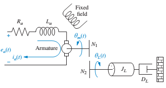
FIGURE P3.11 Motor and load
Expert Solution & Answer
Want to see the full answer?
Check out a sample textbook solution
Students have asked these similar questions
Example-1:
l
D
A uniform rotor of length 0.6 m and diameter 0.4 m is made of steel (density 7810 kg/m³)
is supported by identical short bearings of stiffness 1 MN/m in the horizontal and vertical
directions. If the distance between the bearings is 0.7 m, determine the natural frequencies
and plot whirl speed map.
Solution:
B
find the laplace transform for the
flowing function
2(1-e)
Ans. F(s)=-
S
12)
k
0
Ans. F(s)=
k
s(1+e)
0 a
2a 3a 4a
13)
2+
Ans. F(s)=
1
s(1+e")
3
14) f(t)=1, 0
Find the solution of the following Differential Equations
Using Laplace Transforms
1) 4y+2y=0.
y(0)=2.
y'(0)=0.
2) y+w²y=0,
(0)=A,
y'(0)=B.
3) +2y-8y 0.
y(0)=1.
y'(0)-8.
4)-2-3y=0,
y(0)=1.
y'(0)=7.
5) y-ky'=0,
y(0)=2,
y'(0)=k.
6) y+ky'-2k²y=0,
y(0)=2,
y'(0) = 2k.
7) '+4y=0,
y(0)=2.8
8) y+y=17 sin(21),
y(0)=-1.
9) y-y-6y=0,
y(0)=6,
y'(0)=13.
10) y=0.
y(0)=4,
y' (0)=0.
11) -4y+4y-0,
y(0)=2.1.
y'(0)=3.9
12) y+2y'+2y=0,
y(0)=1,
y'(0)=-3.
13) +7y+12y=21e".
y(0)=3.5.
y'(0)=-10.
14) "+9y=10e".
y(0)=0,
y'(0)=0.
15) +3y+2.25y=91' +64.
y(0)=1.
y'(0) = 31.5
16)
-6y+5y-29 cos(2t).
y(0)=3.2,
y'(0)=6.2
17) y+2y+2y=0,
y(0)=0.
y'(0)=1.
18) y+2y+17y=0,
y(0)=0.
y'(0)=12.
19) y"-4y+5y=0,
y(0)=1,
y'(0)=2.
20) 9y-6y+y=0,
(0)-3,
y'(0)=1.
21) -2y+10y=0,
y(0)=3,
y'(0)=3.
22) 4y-4y+37y=0,
y(0)=3.
y'(0)=1.5
23) 4y-8y+5y=0,
y(0)=0,
y'(0)=1.
24)
++1.25y-0,
y(0)=1,
y'(0)=-0.5
25) y 2 cos(r).
y(0)=2.
y'(0) = 0.
26)
-4y+3y-0,
y(0)=3,
y(0) 7.
27) y+2y+y=e
y(0)=0.
y'(0)=0.
28) y+2y-3y=10sinh(27),
y(0)=0.
y'(0)=4.
29)…
Chapter 3 Solutions
CONTROL SYSTEMS ENGINEERING - WILEYPLUS
Ch. 3 - Prob. 1RQCh. 3 - State an advantage of the transfer function...Ch. 3 - Define state variables.Ch. 3 - Define state.Ch. 3 - Define state vector.Ch. 3 - Define state space.Ch. 3 - What is required to represent a system in state...Ch. 3 - 8. An eighth-order system would be represented in...Ch. 3 - If the state equations are a system of first-order...Ch. 3 - Prob. 10RQ
Ch. 3 - What factors influence the choice of state...Ch. 3 - What is a convenient choice of state variables for...Ch. 3 - If an electrical network has three energy-storage...Ch. 3 - Prob. 14RQCh. 3 - Prob. 1PCh. 3 - Represent the electrical network shown in Figure...Ch. 3 - Prob. 3PCh. 3 - Represent the system shown in Figure P3.4 in state...Ch. 3 - Represent the rotational mechanical system shown...Ch. 3 - Represent the system shown in Figure P3.7 in state...Ch. 3 - 8. Show that the system of Figure 3.7 in the text...Ch. 3 - Find the state-space representation in...Ch. 3 - MATLAB ML 10. Repeat Problem 9 using MATLAB....Ch. 3 - For each system shown in Figure P3.9, write the...Ch. 3 - MATLAB ML
12. Repeat Problem 11 using MATLAB....Ch. 3 - 13. Represent the following transfer function in...Ch. 3 - Find the transfer function G(s) = Y(s)/R(s) for...Ch. 3 - MATLAB ML
15. Use MATLAB to find the transfer...Ch. 3 - 17. A missile in flight, as shown in Figure P3.10,...Ch. 3 - Given the dc servomotor and load shown in Figure...Ch. 3 - Prob. 20PCh. 3 - Prob. 23PCh. 3 - Experiments to identify precision grip dynamics...Ch. 3 - State-space representations are, in general, not...Ch. 3 - Figure P3.16 shows a schematic description of the...Ch. 3 - Prob. 28PCh. 3 - A single-pole oil cylinder valve contains a spool...Ch. 3 - Figure P3.17 shows a free-body diagram of an...Ch. 3 - 33. Parabolic trough collector. A transfer...
Knowledge Booster


Learn more about
Need a deep-dive on the concept behind this application? Look no further. Learn more about this topic, mechanical-engineering and related others by exploring similar questions and additional content below.Similar questions
- Auto Controls A union feedback control system has the following open loop transfer function where k>0 is a variable proportional gain i. for K = 1 , derive the exact magnitude and phase expressions of G(jw). ii) for K = 1 , identify the gaincross-over frequency (Wgc) [where IG(jo))| 1] and phase cross-overfrequency [where <G(jw) = - 180]. You can use MATLAB command "margin" to obtain there quantities. iii) Calculate gain margin (in dB) and phase margin (in degrees) ·State whether the closed-loop is stable for K = 1 and briefly justify your answer based on the margin . (Gain marginPhase margin) iv. what happens to the gain margin and Phase margin when you increase the value of K?you You can use for loop in MATLAB to check that.Helpful matlab commands : if, bode, margin, rlocus NO COPIED SOLUTIONSarrow_forwardThe 120 kg wheel has a radius of gyration of 0.7 m. A force P with a magnitude of 50 N is applied at the edge of the wheel as seen in the diagram. The coefficient of static friction is 0.3, and the coefficient of kinetic friction is 0.25. Find the acceleration and angular acceleration of the wheel.arrow_forwardAuto Controls Using MATLAB , find the magnitude and phase plot of the compensators NO COPIED SOLUTIONSarrow_forward
- 4-81 The corner shown in Figure P4-81 is initially uniform at 300°C and then suddenly exposed to a convection environment at 50°C with h 60 W/m². °C. Assume the = 2 solid has the properties of fireclay brick. Examine nodes 1, 2, 3, 4, and 5 and deter- mine the maximum time increment which may be used for a transient numerical calculation. Figure P4-81 1 2 3 4 1 cm 5 6 1 cm 2 cm h, T + 2 cmarrow_forwardAuto Controls A union feedback control system has the following open loop transfer function where k>0 is a variable proportional gain i. for K = 1 , derive the exact magnitude and phase expressions of G(jw). ii) for K = 1 , identify the gaincross-over frequency (Wgc) [where IG(jo))| 1] and phase cross-overfrequency [where <G(jw) = - 180]. You can use MATLAB command "margin" to obtain there quantities. iii) Calculate gain margin (in dB) and phase margin (in degrees) ·State whether the closed-loop is stable for K = 1 and briefly justify your answer based on the margin . (Gain marginPhase margin) iv. what happens to the gain margin and Phase margin when you increase the value of K?you You can use for loop in MATLAB to check that.Helpful matlab commands : if, bode, margin, rlocus NO COPIED SOLUTIONSarrow_forwardAuto Controls Hand sketch the root Focus of the following transfer function How many asymptotes are there ?what are the angles of the asymptotes?Does the system remain stable for all values of K NO COPIED SOLUTIONSarrow_forward
- Please draw the section view of the following problemsarrow_forward7) Please draw the front, top and side view for the following object. Please cross this line outarrow_forwardA 10-kg box is pulled along P,Na rough surface by a force P, as shown in thefigure. The pulling force linearly increaseswith time, while the particle is motionless att = 0s untilit reaches a maximum force of100 Nattimet = 4s. If the ground has staticand kinetic friction coefficients of u, = 0.6 andHU, = 0.4 respectively, determine the velocityof the A 1 0 - kg box is pulled along P , N a rough surface by a force P , as shown in the figure. The pulling force linearly increases with time, while the particle is motionless at t = 0 s untilit reaches a maximum force of 1 0 0 Nattimet = 4 s . If the ground has static and kinetic friction coefficients of u , = 0 . 6 and HU , = 0 . 4 respectively, determine the velocity of the particle att = 4 s .arrow_forward
arrow_back_ios
SEE MORE QUESTIONS
arrow_forward_ios
Recommended textbooks for you
 Elements Of ElectromagneticsMechanical EngineeringISBN:9780190698614Author:Sadiku, Matthew N. O.Publisher:Oxford University Press
 Mechanics of Materials (10th Edition)Mechanical EngineeringISBN:9780134319650Author:Russell C. HibbelerPublisher:PEARSON
 Thermodynamics: An Engineering ApproachMechanical EngineeringISBN:9781259822674Author:Yunus A. Cengel Dr., Michael A. BolesPublisher:McGraw-Hill Education
 Control Systems EngineeringMechanical EngineeringISBN:9781118170519Author:Norman S. NisePublisher:WILEY
 Mechanics of Materials (MindTap Course List)Mechanical EngineeringISBN:9781337093347Author:Barry J. Goodno, James M. GerePublisher:Cengage Learning
 Engineering Mechanics: StaticsMechanical EngineeringISBN:9781118807330Author:James L. Meriam, L. G. Kraige, J. N. BoltonPublisher:WILEY
Elements Of Electromagnetics
Mechanical Engineering
ISBN:9780190698614
Author:Sadiku, Matthew N. O.
Publisher:Oxford University Press
Mechanics of Materials (10th Edition)
Mechanical Engineering
ISBN:9780134319650
Author:Russell C. Hibbeler
Publisher:PEARSON
Thermodynamics: An Engineering Approach
Mechanical Engineering
ISBN:9781259822674
Author:Yunus A. Cengel Dr., Michael A. Boles
Publisher:McGraw-Hill Education
Control Systems Engineering
Mechanical Engineering
ISBN:9781118170519
Author:Norman S. Nise
Publisher:WILEY
Mechanics of Materials (MindTap Course List)
Mechanical Engineering
ISBN:9781337093347
Author:Barry J. Goodno, James M. Gere
Publisher:Cengage Learning
Engineering Mechanics: Statics
Mechanical Engineering
ISBN:9781118807330
Author:James L. Meriam, L. G. Kraige, J. N. Bolton
Publisher:WILEY
Ch 2 - 2.2.2 Forced Undamped Oscillation; Author: Benjamin Drew;https://www.youtube.com/watch?v=6Tb7Rx-bCWE;License: Standard youtube license