
Concept explainers
Videos
The missing values in the given table.
Answer to Problem 4PP
| Primary | Secondary | Load |
| EP = 23000 V | EP = 120 V | EP = 208 V |
| IP = 0.626A | IP = 120.08 A | IP = 69.33 A |
| EL = 23000 V | EL = 208 V | EL = 208 V |
| IL = 1.084 A | IL = 120.08 A | IL = 120.08 A |
| Ratio = 191.52:1 | Z = 3 Ω |
Explanation of Solution
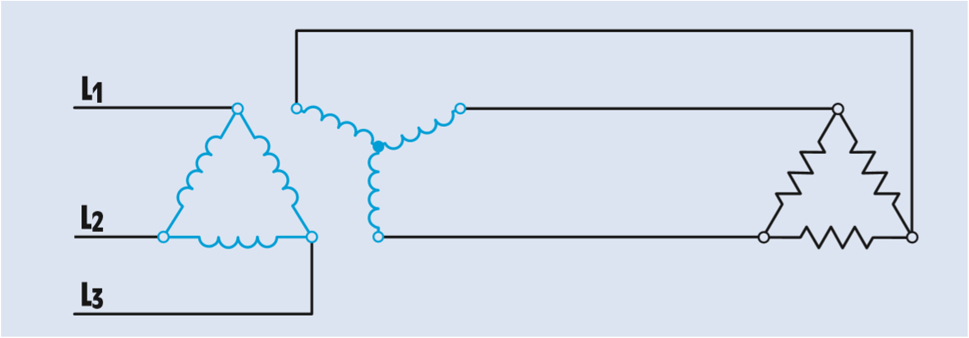
In the figure, three single-phase transformers have been connected to form a delta–wye bank.
The primary is connected to a three-phase line of 23000 V.
The secondary voltage is 208 V.
A three-phase resistive load with an impedance of 3 Ω per phase is connected to the secondary of the transformer.
The primary windings of the three single-phase transformers are connected to form a delta connection. In a delta connection, the phase voltage is equal to line voltage.
The secondary windings are connected as a wye. In a wye connection, the phase voltage is less than the line voltage by a factor of 1.732 (the square root of 3). Therefore, the phase value of the primary voltage can be calculated using the formula
The turns ratio can be calculated by comparing the phase voltage of the primary with the phase voltage of the secondary:
The load is connected directly to the output of the secondary. The line voltage applied to the load must therefore be the same as the line voltage of the secondary:
The load bank is connected in a delta connection. The voltage across the phase of the load bank will equal to the line voltage.
The phase current of the load can be calculated using Ohm’s law:
The amount of line current supplying a delta-connected load will be 1.732 times the phase current of the load:
Since the secondary of the transformer is supplying current to only one load, the line current of the secondary will be the same as the line current of the load:
The phase current in a wye connection is equal to the line current.
The phase current of the transformer primary can now be calculated using the phase current of the secondary and the turns ratio. Because the primary has a higher voltage than the secondary, it will have a lower current. (Volts times amperes input must equal volts times amperes output.)
All the transformed values of voltage and current take place across the phases, the primary has a phase current of 6.68 A. In a delta connection, the line current is 1.732 times the phase current:
Want to see more full solutions like this?
Chapter 29 Solutions
TEXTBOOK OF ELECTRICITY W/MINDTAP >BI<


- i need helppp pleasearrow_forwardsolve and show workarrow_forward2) (15pts) In a PAM baseband digital communication system, an M-ary system has a channel bandwidth of 2 KHz. The channel introduces 10dB of losses and AWGN noise with a power spectral density of 1*10-6 W/Hz. The application requires a bit rate of 4.8 Kbps and BER of less than 10^-6. Estimate the require transmit power.arrow_forward
- i need helppp pleasearrow_forward1) (2pts) If you know you have a bad clock (lots of jitter) and you are not bandwidth constrained, you should: (Circle the correct answer) a) Set the roll off factor to zero b) Set the roll off factor to ½ c) Set the roll off factor to one 2) (2pts) Short answer: Why do we use M-ary modulation? 3) (4 pts) Short answer: The application engineer comes to your desk and says that the error rate is too high and must be reduced for the application to function correctly. The system is battery operated. What do you tell them is the trade- off?arrow_forwardi need helppp pleasearrow_forward
- 5) (20 pts) You are testing a system that has pulse shape shown below for Logic 1 and Logic 0. You are connecting the transmitter to an oscilloscope which is set up to display the resulting eye-diagram of the system. Sketch what you would expect to see on the oscilloscope for an ideal system (an ideal system is noiseless and jitter free) Logic 1 3 volts Time 0 Ть Logic 0 0 Ть Time -2 voltsarrow_forward4. (20 pts) You are given a channel with the following impulse response. Determine the set of equations that will be used to determine the coefficients of a Zero-Forcing Linear Equalizer. DO NOT SOLVE FOR THE COEFFICIENTS. Just show the set of equation that would be used to solved the coefficients. 0 m≤-31 -0.33 m = -2 .25 m = -1 h(mb) = 1 m = 0 -0.45 m = 1 0.5 m = 2 0 m≥3arrow_forwardI need help understanding part B. See attached photo.arrow_forward
- i need helppp pleasearrow_forward3) (30pts) An application requires a bit rate of 18.2 Kbps and an error rate of less than 104. The channel has a noise power spectral density of 10-8 W/Hz. The channel attenuates the power in the signal by 5 dB. The system uses binary PAM baseband digital communication system with the minimum required bandwidth and a roll-off factor of 0.319. a) (10 pts) What is the estimated minimum required signal power (Pt) at the transmitter?arrow_forwardi need helppp pleasearrow_forward
 Introductory Circuit Analysis (13th Edition)Electrical EngineeringISBN:9780133923605Author:Robert L. BoylestadPublisher:PEARSON
 Delmar's Standard Textbook Of ElectricityElectrical EngineeringISBN:9781337900348Author:Stephen L. HermanPublisher:Cengage Learning
 Programmable Logic ControllersElectrical EngineeringISBN:9780073373843Author:Frank D. PetruzellaPublisher:McGraw-Hill Education
 Fundamentals of Electric CircuitsElectrical EngineeringISBN:9780078028229Author:Charles K Alexander, Matthew SadikuPublisher:McGraw-Hill Education
 Electric Circuits. (11th Edition)Electrical EngineeringISBN:9780134746968Author:James W. Nilsson, Susan RiedelPublisher:PEARSON
 Engineering ElectromagneticsElectrical EngineeringISBN:9780078028151Author:Hayt, William H. (william Hart), Jr, BUCK, John A.Publisher:Mcgraw-hill Education,