
Concept explainers
Videos
The missing values in the given table.
Answer to Problem 4PP
| Primary | Secondary | Load |
| EP = 23000 V | EP = 120 V | EP = 208 V |
| IP = 0.626A | IP = 120.08 A | IP = 69.33 A |
| EL = 23000 V | EL = 208 V | EL = 208 V |
| IL = 1.084 A | IL = 120.08 A | IL = 120.08 A |
| Ratio = 191.52:1 | Z = 3 Ω |
Explanation of Solution
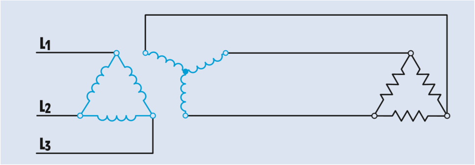
In the figure, three single-phase transformers have been connected to form a delta–wye bank.
The primary is connected to a three-phase line of 23000 V.
The secondary voltage is 208 V.
A three-phase resistive load with an impedance of 3 Ω per phase is connected to the secondary of the transformer.
The primary windings of the three single-phase transformers are connected to form a delta connection. In a delta connection, the phase voltage is equal to line voltage.
The secondary windings are connected as a wye. In a wye connection, the phase voltage is less than the line voltage by a factor of 1.732 (the square root of 3). Therefore, the phase value of the primary voltage can be calculated using the formula
The turns ratio can be calculated by comparing the phase voltage of the primary with the phase voltage of the secondary:
The load is connected directly to the output of the secondary. The line voltage applied to the load must therefore be the same as the line voltage of the secondary:
The load bank is connected in a delta connection. The voltage across the phase of the load bank will equal to the line voltage.
The phase current of the load can be calculated using Ohm’s law:
The amount of line current supplying a delta-connected load will be 1.732 times the phase current of the load:
Since the secondary of the transformer is supplying current to only one load, the line current of the secondary will be the same as the line current of the load:
The phase current in a wye connection is equal to the line current.
The phase current of the transformer primary can now be calculated using the phase current of the secondary and the turns ratio. Because the primary has a higher voltage than the secondary, it will have a lower current. (Volts times amperes input must equal volts times amperes output.)
All the transformed values of voltage and current take place across the phases, the primary has a phase current of 6.68 A. In a delta connection, the line current is 1.732 times the phase current:
Want to see more full solutions like this?
Chapter 29 Solutions
EBK DELMAR'S STANDARD TEXTBOOK OF ELECT


- For the oscillator resonance circuit shown in Fig. (5), derive the oscillation frequency Feedback and open-loop gains. L₁ 5 mH (a) ell +10 V R₁ ww R3 S C2 HH 1 με 1000 pF 100 pF R₂ 1 με RA H (b) +9 V R4 CA 470 pF C₁ R3 HH 1 με R₁ ww L₁ 000 1.5 mH R₂ ww Hi 1 μF L2 m 10 mHarrow_forwardExpert handwritten solution onlyarrow_forwardB. For the oscillator circuit shown in frequency, feedback and open-loop gains. +10 V name the circuit, derive and find the oscillation P.Av +9 V -000 4₁ 5 mH w R₁ C₂ HH 1 με w 100 pF R₂ T R CA www. 470 pF w ww www 1000 pF HH 1μF C₁ HH 1μF Ra ww HI 4₁ 000 1.5 mH H 4 AF 000 10 mHarrow_forward
- R₁ W +10 V R3 +9 V C₂ R₁ CA C₁ 470 pF HH 1000 pF HH 1 με C4 1 μF 1 uF C₁ R₂ R4 100 pF Find Open-loop Jain L₁ 5 mH (a) Av=S,B={" H R₁₂ ✓ ww (b) R₁ L₁ 000 1.5 mH R₂ H 1 uF 12 10 mHarrow_forwardA) Calculate the efficiency of the test transformer at the resistive loads (X-25%, 50%, 75%, 100%, 125% full load). B) From part (A) draw the plot (efficiency Vs power output) of the transformer. C) Discuss the plot of part (B).arrow_forwarda- Determine fH; and Ho b- Find fg and fr. c- Sketch the frequency response for the high-frequency region using a Bode plot and determine the cutoff frequency. Ans: 277.89 KHz; 2.73 MHz; 895.56 KHz; 107.47 MHz. 14V Cw=5pF Cwo-8pF Coc-12 pF 5.6kQ Ch. 40. pF C-8pF 68kQ 0.47µF Vo 0.82 kQ V₁ B=120 0.47µF www 3.3kQ 10kQ 1.2kQ =20µF Narrow_forward
- Using D flip-flops, design a synchronous counter. The counter counts in the sequence 1,3,5,7, 1,7,5,3,1,3,5,7,.... when its enable input x is equal to 1; otherwise, the counter. This counter is for individual settings only need the state diagram and need the state table to use 16 states from So to S15.arrow_forward: A sequential network has one input (X) and two outputs (Z1 and Z2). An output Z1 Z2 = 10 occurs every time the input sequence 1011 is completed. An output Z1 Z2 = 01 occurs every time the input sequence 0101 is completed. Otherwise Z1 Z2 = 0 Find Moore state diagram with minimum number of states: a) When overlap is allowed. b) When overlap is not allowed. I need a step by step printable solution that uses sequences on the same drawing.arrow_forward1. Consider a negative unity-feedback control system whose plant transfer function is type- 1. Suppose you want to build a lead compensator so that -3 ± 5j are dominant poles. You observed that the angle deficiency at the desired dominant pole is 50°. Compute a 's+b' and b of the lead compensator (s+ 2) so that the error constant Ky is maximized. In other words, design the lead compensator in a way so that the steady-state error for ramp input is minimumarrow_forward
 Introductory Circuit Analysis (13th Edition)Electrical EngineeringISBN:9780133923605Author:Robert L. BoylestadPublisher:PEARSON
 Delmar's Standard Textbook Of ElectricityElectrical EngineeringISBN:9781337900348Author:Stephen L. HermanPublisher:Cengage Learning
 Programmable Logic ControllersElectrical EngineeringISBN:9780073373843Author:Frank D. PetruzellaPublisher:McGraw-Hill Education
 Fundamentals of Electric CircuitsElectrical EngineeringISBN:9780078028229Author:Charles K Alexander, Matthew SadikuPublisher:McGraw-Hill Education
 Electric Circuits. (11th Edition)Electrical EngineeringISBN:9780134746968Author:James W. Nilsson, Susan RiedelPublisher:PEARSON
 Engineering ElectromagneticsElectrical EngineeringISBN:9780078028151Author:Hayt, William H. (william Hart), Jr, BUCK, John A.Publisher:Mcgraw-hill Education,