
Electric Motor Control
10th Edition
ISBN: 9781133702818
Author: Herman
Publisher: CENGAGE L
expand_more
expand_more
format_list_bulleted
Concept explainers
Videos
Textbook Question
Chapter 29, Problem 1SQ
Indicate the correct terminal markings for a star-delta motor on Figure 29–9.
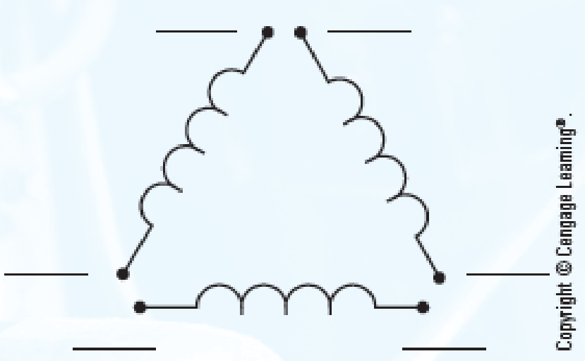
FIG. 29–9
Expert Solution & Answer
To determine
Specify the correct terminal markings of the star-delta motor in Figure 29-9.
Explanation of Solution
Star-delta motors:
The construction of star-delta motor is similar like standard type of squirrel cage motors. In star-delta motor, two ends of each of the three windings are brought out to terminals.
Refer Figure 29-9 in the textbook for the star-delta motor circuit. Modify the figure by mentioning the all-terminal markings and the modified circuit diagram as shown in Figure 1.
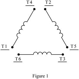
In Figure 1, T1, T2, T3, T4, T5, and T6 are the six leads of motor.
Conclusion:
Thus, the correct terminal markings are mentioned in the star-delta motor.
Want to see more full solutions like this?
Subscribe now to access step-by-step solutions to millions of textbook problems written by subject matter experts!
Students have asked these similar questions
Q1/Sketch the root locus for the system shown in Figure 1 and find the following:
a. The exact point and gain where the locus crosses the jo-axis b. The breakaway point
on the real axis c. The range of K within which the system is stable d. Angles of
departure and arrival
R(s) +
K(s²-4s +20)
C(s)
(s+2)(s + 4)
Exam2
Subject: (Numerical Analysis)
Class: Third
Date: 27/4/2025
Time: 60 minutes
Q1. For what values of k does this system of equations has no solution? (use Gauss-Jordan eliminations)
kx + y + z = 1
x+ky + z = 1
x+y+kz=1
Consider the Difference equation of a causal Linear time-invariant (LTI) system given
by: (y(n) - 1.5y(n - 1) + 0.5y(n = 2) = x(n)
a) Implement the difference equation model of this system.
b) Find the system transfer function H(z).
c) For an input x(n) = 8(n), determine the output response y(n).
d) Verify the initial value theorem y(0) with part (c).
Knowledge Booster


Learn more about
Need a deep-dive on the concept behind this application? Look no further. Learn more about this topic, electrical-engineering and related others by exploring similar questions and additional content below.Similar questions
- Q5B. Find the type of the controller in the following figures and use real values to find the transfer function of three of them[ Hint Pi,Pd and Lead,lag are found so put the controller with its corresponding compensator]. R₁ R₂ Rz HE C2 RA HE R₁ R2 RA とarrow_forwardQ1// Sketch the root locus for the unity feedback system. Where G(s)=)= K S3+252 +25 and find the following a. Sketch the asymptotes b. The exact point and gain where the locus crosses the jo-axis c. The breakaway point on the real axis d. The range of K within which the system is stable e. Angles of departure and arrival.arrow_forwardDetermine X(w) for the given function shown in Figure (1) by applying the differentiation property of the Fourier Transform. Figure (1) -1 x(t)arrow_forward
- Can you solve a question with a drawing Determine X(w) for the given function shown in Figure (1) by applying the differentiation property of the Fourier Transform. Figure (1) -1 x(t)arrow_forwardAn inductor has a current flow of 3 A when connected to a 240 V, 60 Hz power line. The inductor has a wire resistance of 15 Find the Q of the inductorarrow_forwardصورة من s94850121arrow_forward
- The joint density function of two continuous random variables X and Yis: p(x, y) = {Keós (x + y) Find (i) the constant K 0 2 0arrow_forwardShow all the steps please, Solve for the current through R2 if E2 is replaced by a current source of 10mA using superposition theorem. R5=470Ω R2=1000Ω R6=820Ωarrow_forwardPlease solve it by explaining the steps. I am trying to prepare for my exam tomorrow, so any tips and tricks to solve similar problems are highly appreciated. Plus, this is a past exam I am using to prepare.arrow_forwardPlease solve it by explaining the steps. I am trying to prepare for my exam today, so any tips and tricks to solve similar problems are highly appreciated. Plus, this is a past exam I am using to prepare.arrow_forwardIf C is the circle |z|=4 evaluate f f (z)dz for each of the following functions using residue. 1 f(z) = z(z²+6z+4)arrow_forwardIf C is the circle |z|=4 evaluate ff(z)dz for each of the following functions using residue. f(z) z(z²+6z+4)arrow_forwardarrow_back_iosSEE MORE QUESTIONSarrow_forward_ios
Recommended textbooks for you
 Electricity for Refrigeration, Heating, and Air C...Mechanical EngineeringISBN:9781337399128Author:Russell E. SmithPublisher:Cengage Learning
Electricity for Refrigeration, Heating, and Air C...
Mechanical Engineering
ISBN:9781337399128
Author:Russell E. Smith
Publisher:Cengage Learning
How Electric Motors Work - 3 phase AC induction motors ac motor; Author: The Engineering Mindset;https://www.youtube.com/watch?v=59HBoIXzX_c;License: Standard Youtube License