
Videos
(a)
The flux graph through the loop.
(a)
Answer to Problem 39P
The flux graph through the loop as a function of time is shown in figure 1.
Explanation of Solution
Given:
The length of the rectangular loop,
The widthof the rectangular loop,
The stance of the rectangular loop,
The speed of the rectangular loop,
The magnetic field of the rectangular loop,
Formula used:
The formula for flux through the loop as a function of time is given by,
The expression for the time required to enter into uniform magnetic field is given by,
The expression of flux in terms of the length is given by,
Calculation:
The time required to enter into uniform magnetic field is calculated as,
The flux
For,
For,
From equation (1) and (2)
Now,
The induced current through the loop as a function of time is shown in figure 1.
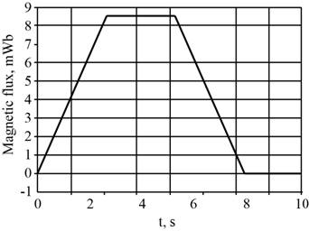
Figure 1
Conclusion:
The graph of induced emf through the loop as a function of time is shown in the figure 1.
(b)
The graph of induced emf and current through the loop.
(b)
Answer to Problem 39P
The graph of induced emf and current through the loop is shown in the figure 2 and 3.
Explanation of Solution
Formula used:
The formula for induced emfthrough the loop is given by,
Calculation:
The induced emf through the loop when
Theinduced emfthrough the loop when
The current through the loop when
The graph for the emf is shown in figure 2.
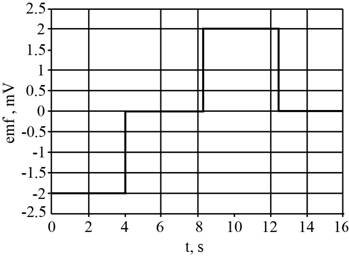
Figure 2
The expression for the value of current is given by,
The graph for the current is shown in figure 3.
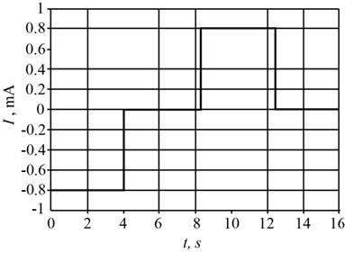
Figure 3
Conclusion:
The graph of induced emfand current through the loop is shown in the figure 2 and 3.
Want to see more full solutions like this?
Chapter 28 Solutions
EBK PHYSICS FOR SCIENTISTS AND ENGINEER


- Two complex values are z1=8 + 8i, z2=15 + 7 i. z1∗ and z2∗ are the complex conjugate values. Any complex value can be expessed in the form of a+bi=reiθ. Find θ for (z1-z∗2)/z1+z2∗. Find r and θ for (z1−z2∗)z1z2∗ Please show all stepsarrow_forwardCalculate the center of mass of the hollow cone shown below. Clearly specify the origin and the coordinate system you are using. Z r Y h Xarrow_forward12. If all three collisions in the figure below are totally inelastic, which will cause more damage? (think about which collision has a larger amount of kinetic energy dissipated/lost to the environment? I m II III A. I B. II C. III m m v brick wall ע ע 0.5v 2v 0.5m D. I and II E. II and III F. I and III G. I, II and III (all of them) 2marrow_forward
- 11. If all three collisions in the figure below are totally inelastic, which brings the car of mass (m) on the left to a halt? I m II III m m ע ע ע brick wall 0.5v 2m 2v 0.5m A. I B. II C. III D. I and II E. II and III F. I and III G. I, II and III (all of them)arrow_forwardHow can you tell which vowel is being produced here ( “ee,” “ah,” or “oo”)? Also, how would you be able to tell for the other vowels?arrow_forwardYou want to fabricate a soft microfluidic chip like the one below. How would you go about fabricating this chip knowing that you are targeting a channel with a square cross-sectional profile of 200 μm by 200 μm. What materials and steps would you use and why? Disregard the process to form the inlet and outlet. Square Cross Sectionarrow_forward
- 1. What are the key steps involved in the fabrication of a semiconductor device. 2. You are hired by a chip manufacturing company, and you are asked to prepare a silicon wafer with the pattern below. Describe the process you would use. High Aspect Ratio Trenches Undoped Si Wafer P-doped Si 3. You would like to deposit material within a high aspect ratio trench. What approach would you use and why? 4. A person is setting up a small clean room space to carry out an outreach activity to educate high school students about patterning using photolithography. They obtained a positive photoresist, a used spin coater, a high energy light lamp for exposure and ordered a plastic transparency mask with a pattern on it to reduce cost. Upon trying this set up multiple times they find that the full resist gets developed, and they are unable to transfer the pattern onto the resist. Help them troubleshoot and find out why pattern of transfer has not been successful. 5. You are given a composite…arrow_forwardTwo complex values are z1=8 + 8i, z2=15 + 7 i. z1∗ and z2∗ are the complex conjugate values. Any complex value can be expessed in the form of a+bi=reiθ. Find r and θ for (z1-z∗2)/z1+z2∗. Find r and θ for (z1−z2∗)z1z2∗ Please show all stepsarrow_forwardAn electromagnetic wave is traveling through vacuum in the positive x direction. Its electric field vector is given by E=E0sin(kx−ωt)j^,where j^ is the unit vector in the y direction. If B0 is the amplitude of the magnetic field vector, find the complete expression for the magnetic field vector B→ of the wave. What is the Poynting vector S(x,t), that is, the power per unit area associated with the electromagnetic wave described in the problem introduction? Give your answer in terms of some or all of the variables E0, B0, k, x, ω, t, and μ0. Specify the direction of the Poynting vector using the unit vectors i^, j^, and k^ as appropriate. Please explain all stepsarrow_forward

 Glencoe Physics: Principles and Problems, Student...PhysicsISBN:9780078807213Author:Paul W. ZitzewitzPublisher:Glencoe/McGraw-Hill
 Physics for Scientists and Engineers: Foundations...PhysicsISBN:9781133939146Author:Katz, Debora M.Publisher:Cengage Learning
 Principles of Physics: A Calculus-Based TextPhysicsISBN:9781133104261Author:Raymond A. Serway, John W. JewettPublisher:Cengage Learning
 Physics for Scientists and Engineers with Modern ...PhysicsISBN:9781337553292Author:Raymond A. Serway, John W. JewettPublisher:Cengage Learning
 College PhysicsPhysicsISBN:9781938168000Author:Paul Peter Urone, Roger HinrichsPublisher:OpenStax College