
Concept explainers
Explain the process how 230/460-volt motor is used as a part winding motor.
Explanation of Solution
Part winding motor:
The part winding motor has two sets of identical windings which are connected in parallel with each other. The two identical windings are energized in a sequence to produce the reduced starting current and the reduced starting torque.
Dual voltage motor:
The dual voltage motor has two sets of windings (not identical) which are connected either in parallel or in series. When the 230/460-volt motor operates with the part winding starter, it is intended to connect the two sets of windings in parallel (voltage ratio is 1:2). An each set of windings is connected either in Y or delta connection.
The dual voltage motor can operate with different power supply voltages. When the dual voltage motor’s two sets of windings are connected in parallel, the motor can operate with low voltage connection. When the windings are connected in series, the motor can operate with high voltage.
230/460-volt motor as a part winding motor:
230/460-volt dual voltage motor can be used as a part winding motor with low voltage connection. At the starting of the motor, the low voltage supply is connected to the one set of winding. As soon as the motor reaches to the normal speed, apply the power to the other set of winding (the other winding from the parallel windings) in the running conditions for the normal running operation of the motor. The motor runs with reduced starting current and the reduced starting torque after both the windings are energized in a sequence.
The part winding starter is a reduced voltage starter and used in the starting process of the 230/460-volt part winding motor.
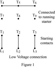
Refer to Figure 28.3 in textbook where the 230/460-volt motor can be used as a part winding motor with low voltage connection. One set of winding terminals
Figure 1 shows the low voltage connection of a part winding motor.
Conclusion:
Thus, the 230/460-volt motor can be used as a part winding motor.
Want to see more full solutions like this?
Chapter 28 Solutions
Electric Motor Control


- i need helppp pleasearrow_forward1) (2pts) If you know you have a bad clock (lots of jitter) and you are not bandwidth constrained, you should: (Circle the correct answer) a) Set the roll off factor to zero b) Set the roll off factor to ½ c) Set the roll off factor to one 2) (2pts) Short answer: Why do we use M-ary modulation? 3) (4 pts) Short answer: The application engineer comes to your desk and says that the error rate is too high and must be reduced for the application to function correctly. The system is battery operated. What do you tell them is the trade- off?arrow_forwardi need helppp pleasearrow_forward
- 5) (20 pts) You are testing a system that has pulse shape shown below for Logic 1 and Logic 0. You are connecting the transmitter to an oscilloscope which is set up to display the resulting eye-diagram of the system. Sketch what you would expect to see on the oscilloscope for an ideal system (an ideal system is noiseless and jitter free) Logic 1 3 volts Time 0 Ть Logic 0 0 Ть Time -2 voltsarrow_forward4. (20 pts) You are given a channel with the following impulse response. Determine the set of equations that will be used to determine the coefficients of a Zero-Forcing Linear Equalizer. DO NOT SOLVE FOR THE COEFFICIENTS. Just show the set of equation that would be used to solved the coefficients. 0 m≤-31 -0.33 m = -2 .25 m = -1 h(mb) = 1 m = 0 -0.45 m = 1 0.5 m = 2 0 m≥3arrow_forwardI need help understanding part B. See attached photo.arrow_forward
- i need helppp pleasearrow_forward3) (30pts) An application requires a bit rate of 18.2 Kbps and an error rate of less than 104. The channel has a noise power spectral density of 10-8 W/Hz. The channel attenuates the power in the signal by 5 dB. The system uses binary PAM baseband digital communication system with the minimum required bandwidth and a roll-off factor of 0.319. a) (10 pts) What is the estimated minimum required signal power (Pt) at the transmitter?arrow_forwardi need helppp pleasearrow_forward
- i need helppp pleasearrow_forwardi need helppp pleasearrow_forward1a) (5pts) Suppose X is a Gaussian random variable with a mean of 2 and a variance of 9. What is the probability X is greater than 2. 1b) (5pts) Suppose X is a Gaussian random variable with a mean of 2 and a variance of 9. Using the Q-function, determine Prob{-4-2} Leave your answer in terms of the Q-function; do not evaluate it.arrow_forward

 Delmar's Standard Textbook Of ElectricityElectrical EngineeringISBN:9781337900348Author:Stephen L. HermanPublisher:Cengage Learning
 Electricity for Refrigeration, Heating, and Air C...Mechanical EngineeringISBN:9781337399128Author:Russell E. SmithPublisher:Cengage Learning