
Concept explainers
Explain the process how 230/460-volt motor is used as a part winding motor.
Explanation of Solution
Part winding motor:
The part winding motor has two sets of identical windings which are connected in parallel with each other. The two identical windings are energized in a sequence to produce the reduced starting current and the reduced starting torque.
Dual voltage motor:
The dual voltage motor has two sets of windings (not identical) which are connected either in parallel or in series. When the 230/460-volt motor operates with the part winding starter, it is intended to connect the two sets of windings in parallel (voltage ratio is 1:2). An each set of windings is connected either in Y or delta connection.
The dual voltage motor can operate with different power supply voltages. When the dual voltage motor’s two sets of windings are connected in parallel, the motor can operate with low voltage connection. When the windings are connected in series, the motor can operate with high voltage.
230/460-volt motor as a part winding motor:
230/460-volt dual voltage motor can be used as a part winding motor with low voltage connection. At the starting of the motor, the low voltage supply is connected to the one set of winding. As soon as the motor reaches to the normal speed, apply the power to the other set of winding (the other winding from the parallel windings) in the running conditions for the normal running operation of the motor. The motor runs with reduced starting current and the reduced starting torque after both the windings are energized in a sequence.
The part winding starter is a reduced voltage starter and used in the starting process of the 230/460-volt part winding motor.
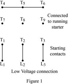
Refer to Figure 28.3 in textbook where the 230/460-volt motor can be used as a part winding motor with low voltage connection. One set of winding terminals
Figure 1 shows the low voltage connection of a part winding motor.
Conclusion:
Thus, the 230/460-volt motor can be used as a part winding motor.
Want to see more full solutions like this?
Chapter 28 Solutions
EBK ELECTRIC MOTOR CONTROL


- Q1/For the unity-feedback system where G (s) = K(s+ 1)(s+ 10) (s+4) (s-6) Sketch the root locus and find the value of K for which the system is closed-loop stable. Also find the break-in and breakaway points.arrow_forwardThe switch K at Figure 4 is closed at t = 0.2 second. Assuming iL(0) = 0, Find iL(t). 10 Ω w i₁(t) 2ix 20 Ω 2H 10u(t) t = 0.2 s Figure 4 Karrow_forwardThe voltage source in the circuit of Fig. P12.31 is, givenby us(t) = [10+5u(t)] V. Determine iL(t) for t ≥ 0, given thatR1 = 1 W, R2 = 1 W, L = 2 H, and C = 1 F.arrow_forward
- Don't use ai to answer I will report you answerarrow_forwardDetermine iL(t) in the circuit of Fig. P12.25, given thatbefore closing the switch uC(0−)=12 V. Also, the element valuesare R = 2 W, L = 1.5 H, and C = 0.5 F.arrow_forwardThe switch in Figure 5 is closed at t = 0 second. Find the voltage of the capacitor, vc, for t> 0. 8Ω t=0 ww + 0.15H + 24U(-t) 80- 2.5mF VC 2A 0.1H Figure 5arrow_forward
- Q1/For the unity-feedback system where G (s) = K(s+ 1)(s+ 10) (s+4) (s-6) G Sketch the root locus and find the value of K for which the system is closed-loop stable. Also find the break-in and breakaway points.arrow_forward12.22 Repeat Problem 12.21, but assume that the switch hadbeen open for a long time and then closed at t = 0. Set the dcsource at 12 mV and the element values at R0 = 5 W, R1 = 10 W,R2 = 20 W, L = 2 H, and C = 0.4 F. question 21(Determine iL(t) in the circuit of Fig. P12.21 for t ≥ 0,given that the switch was opened at t = 0 after it had been closedfor a long time, us = 12 mV, R0 = 5 W, R1 = 10 W, R2 = 20 W,L = 0.2 H, and C = 6 mF.)arrow_forwardIn Figure 1, by considering reference located at node 4, the voltage nodes will be: V1=4, V2= -5, V3=0.5 volts. If we change the location of reference to node 3, find the values for V1, V2, V4, ix, Vo, Vx and power produced by the current sources without conducting detailed node or mesh analyses. 10 www 4A ww 44 4Q 802 w + Vo 4Q 2 3 3ix Figure 1 ww 4Q 5 W4 1.50arrow_forward
- In the Figure 3 a) Find the values for Vi and ix using nodal analysis. b) Find the produced power by the current source. 50 10Ω www 37A 10Ω 20 5 ix V₁ 200 ix Figure 3 ww 100 + 4V1arrow_forward2) By series and parallel combinations find the equivalent capacitance for this circuit. ||15€ Cequivalent -66 6f 6E 12Farrow_forwardQ2/For the unity-feedback system where G(s) = K/[s (s+3) (s+ 5)], find the range of gain, K, for stability, instability, and the value of gain for marginal stability. For marginal stability also. Use the Nyquist criterion.arrow_forward

 Delmar's Standard Textbook Of ElectricityElectrical EngineeringISBN:9781337900348Author:Stephen L. HermanPublisher:Cengage Learning
 Electricity for Refrigeration, Heating, and Air C...Mechanical EngineeringISBN:9781337399128Author:Russell E. SmithPublisher:Cengage Learning