Statics: Engineering Mechanics Statics COE 2001
8th Edition
ISBN: 9781119171263
Author: J.L. Meriam, L.G. Kraige, J.N. Bolton
Publisher: WILEY
expand_more
expand_more
format_list_bulleted
Concept explainers
Videos
Textbook Question
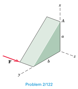
Chapter 2.8, Problem 122P
Determine the moment of force F about point A.
Expert Solution & Answer
Want to see the full answer?
Check out a sample textbook solution
Students have asked these similar questions
Complete the following problems. Show your work/calculations, save as.pdf and upload to the
assignment in Blackboard.
missing information to present a completed program. (Hint: You may have to look up geometry
for the center drill and standard 0.5000 in twist drill to know the required depth to drill).
1. What are the x and y dimensions for the center position of holes 1,2, and 3 in the part shown in
Figure 26.2 (below)?
6.0000
Zero
reference
point
7118
1.0005
1.0000
1.252
Bore
6.0000
.7118
Cbore
0.2180 deep
(3 holes)
2.6563 1.9445
Figure 26.2
026022 (8lot and Drill Part)
(Setup Instructions---
(UNITS: Inches
(WORKPIECE NAT'L SAE 1020 STEEL
(Workpiece: 3.25 x 2.00 x0.75 in. Plate
(PRZ Location 054:
'
XY 0.0 - Upper Left of Fixture
TOP OF PART 2-0
(Tool List
( T02 0.500 IN 4 FLUTE FLAT END MILL
#4 CENTER DRILL
Dashed line indicates-
corner of original stock
( T04
T02
3.000 diam. slot
0.3000 deep.
0.3000 wide
Intended toolpath-tangent-
arc entry and exit sized to
programmer's judgment…
A program to make the part depicted in Figure 26.A has been created, presented in figure 26.B, but some information still needs to be filled in. Compute the tool locations, depths, and other missing information to present a completed program. (Hint: You may have to look up geometry for the center drill and standard 0.5000 in twist drill to know the required depth to drill).
We consider a laminar flow induced by an impulsively started infinite flat
plate. The y-axis is normal to the plate. The x- and z-axes form a plane parallel
to the plate. The plate is defined by y = 0. For time t <0, the plate and the flow
are at rest. For t≥0, the velocity of the plate is parallel to the 2-coordinate;
its value is constant and equal to uw. At infinity, the flow is at rest. The flow
induced by the motion of the plate is independent of z.
(a) From the continuity equation, show that v=0 everywhere in the flow and
the resulting momentum equation is
მu
Ət
Note that this equation has the form of a diffusion equation (the same form as
the heat equation).
(b) We introduce the new variables T, Y and U such that
T=kt, Y=k/2y, U = u
where k is an arbitrary constant. In the new system of variables, the solution
is U(Y,T). The solution U(Y,T) is expressed by a function of Y and T and the
solution u(y, t) is expressed by a function of y and t. Show that the functions are
identical.…
Chapter 2 Solutions
Statics: Engineering Mechanics Statics COE 2001
Ch. 2.3 - The force F has a magnitude of 800 N. Express F as...Ch. 2.3 - The force F has a magnitude of 7 kN and acts at...Ch. 2.3 - The slope of the 6.5-kN force F is specified as...Ch. 2.3 - The force F has a magnitude of 1250 lb and has the...Ch. 2.3 - The control rod AP exerts a force F on the sector...Ch. 2.3 - Two forces are applied to the construction bracket...Ch. 2.3 - Two individuals are attempting to relocate a sofa...Ch. 2.3 - A small probe P is gently forced against the...Ch. 2.3 - The y-component of the force F which a person...Ch. 2.3 - Determine the x-y and n-t components of the 13-kip...
Ch. 2.3 - The two structural members, one of which is in...Ch. 2.3 - The guy cables AB and AC are attached to the top...Ch. 2.3 - If the equal tensions T in the pulley cable are...Ch. 2.3 - Two people exert the forces shown on the potted...Ch. 2.3 - A compressive force F is transmitted via the...Ch. 2.3 - A force F of magnitude 800 lb is applied to point...Ch. 2.3 - The two forces shown act in the x-y plane of the...Ch. 2.3 - Determine the x- and y-components of the tension T...Ch. 2.3 - Refer to the mechanism of the previous problem....Ch. 2.3 - Determine the magnitude Fs of the tensile spring...Ch. 2.3 - Determine the resultant R of the two forces...Ch. 2.3 - A sheet of an experimental composite is subjected...Ch. 2.3 - Determine the scalar components Ra and Rb of the...Ch. 2.3 - Determine the components Fa and Fb of the 4-kN...Ch. 2.3 - If the projection Pa and component Fb of the force...Ch. 2.3 - It is desired to remove the spike from the timber...Ch. 2.3 - At what angle must the 800-lb force be applied in...Ch. 2.3 - Power is to be transferred from the pinion A to...Ch. 2.3 - To insert the small cylindrical part into a...Ch. 2.3 - The unstretched length of the spring is r. When...Ch. 2.4 - Determine the moments of the 5-kN force about...Ch. 2.4 - The force of magnitude F acts along the edge of...Ch. 2.4 - The rectangular plate is made up of 1-ft squares...Ch. 2.4 - Calculate the moment of the 250-N force on the...Ch. 2.4 - An experimental device imparts a force of...Ch. 2.4 - A force F of magnitude 60 N is applied to the...Ch. 2.4 - A man uses a crowbar to lift the corner of a hot...Ch. 2.4 - An overhead view of a door is shown. If the...Ch. 2.4 - The 30-N force P is applied perpendicular to the...Ch. 2.4 - A man exerts a force F on the handle of the...Ch. 2.4 - A 32-lb pull T is applied to a cord, which is...Ch. 2.4 - As a trailer is towed in the forward direction,...Ch. 2.4 - Determine the general expressions for the moments...Ch. 2.4 - The mechanism of Prob. 2/15 is repeated here....Ch. 2.4 - Determine the moments of the tension T about point...Ch. 2.4 - In raising the pole from the position shown, the...Ch. 2.4 - The lower lumbar region A of the spine is the part...Ch. 2.4 - A gate is held in the position shown by cable AB....Ch. 2.4 - In order to raise the flagpole OC, a light frame...Ch. 2.4 - Elements of the lower arm are shown in the figure....Ch. 2.4 - As the result of a wind blowing normal to the...Ch. 2.4 - The masthead fitting supports the two forces...Ch. 2.4 - The small crane is mounted along the side of a...Ch. 2.4 - The 120-N force is applied as shown to one end of...Ch. 2.4 - The bent cantilever beam is acted upon by an 8-kN...Ch. 2.4 - The mechanism shown is used to lower disabled...Ch. 2.4 - The asymmetrical support arrangement is chosen for...Ch. 2.4 - The woman maintains a slow steady motion over the...Ch. 2.5 - The caster unit is subjected to the pair of 80-lb...Ch. 2.5 - For F=65lb, compute the combined moment of the two...Ch. 2.5 - The indicated force—couple system is applied to...Ch. 2.5 - Replace the 3.2-kN force by an equivalent...Ch. 2.5 - As part of a test, the two aircraft engines are...Ch. 2.5 - The cantilevered W530150 beam shown is subjected...Ch. 2.5 - Each propeller of the twin-screw ship develops a...Ch. 2.5 - The upper hinge A of the uniform cabinet door has...Ch. 2.5 - A lug wrench is used to tighten a square-head...Ch. 2.5 - The force F is applied at the end of arm ACD,...Ch. 2.5 - A force F of magnitude 50 N is exerted on the...Ch. 2.5 - An overhead view of a portion of an exercise...Ch. 2.5 - The tie-rod AB exerts the 250-N force on the...Ch. 2.5 - The 20-N force F is applied to the handle of the...Ch. 2.5 - An overhead view of the handlebars on an...Ch. 2.5 - The force F is applied to the leg-extension...Ch. 2.5 - The system consisting of the bar OA, two identical...Ch. 2.5 - The device shown is a part of an automobile seat-...Ch. 2.5 - Replace the two cable tensions which act on the...Ch. 2.5 - The force F acts along line MA, where M is the...Ch. 2.6 - Determine the resultant R of the three tension...Ch. 2.6 - Determine the force magnitude F and direction ...Ch. 2.6 - Replace the three horizontal forces and applied...Ch. 2.6 - Determine the equivalent force-couple system at...Ch. 2.6 - Determine the equivalent force-couple system at O...Ch. 2.6 - Determine the height h above the base B at which...Ch. 2.6 - Where does the resultant of the two forces act?Ch. 2.6 - If the resultant of the loads shown passes through...Ch. 2.6 - If the resultant of the two forces and couple M...Ch. 2.6 - If the resultant of the forces shown passes...Ch. 2.6 - Replace the three forces acting on the bent pipe...Ch. 2.6 - Four people are attempting to move a stage...Ch. 2.6 - Replace the three forces which act on the bent bar...Ch. 2.6 - Uneven terrain conditions cause the left front...Ch. 2.6 - A commercial airliner with four jet engines, each...Ch. 2.6 - Determine the x- and y-axis intercepts of the line...Ch. 2.6 - Replace the three cable tensions acting on the...Ch. 2.6 - Determine the resultant R of the three forces...Ch. 2.6 - For the truss loaded as shown, determine the...Ch. 2.6 - Five forces are applied to the beam trolley as...Ch. 2.6 - As part of a design test, the camshaft-drive...Ch. 2.6 - An exhaust system for a pickup truck is shown in...Ch. 2.7 - Express F as a vector in terms of the unit vectors...Ch. 2.7 - Cable AB exerts a force of magnitude F=6kN on...Ch. 2.7 - Express the 5-kN force F as a vector in terms of...Ch. 2.7 - The force F has a magnitude of 300 1b and acts...Ch. 2.7 - If the tension in the gantry-crane hoisting cable...Ch. 2.7 - The turnbuckle is tightened until the tension in...Ch. 2.7 - If the tension in cable AB is 1750 lb, determine...Ch. 2.7 - The tension in the supporting cable AB is T=425N....Ch. 2.7 - The force F has a magnitude of 2 kN and is...Ch. 2.7 - The tension in the supporting cable AB is 10 kN....Ch. 2.7 - If the tension in cable CD is T=675lb, determine...Ch. 2.7 - If the tension in cable DE is T=575N, determine...Ch. 2.7 - Determine the angle between the 200-lb force and...Ch. 2.7 - Compression member AB is used to hold up the...Ch. 2.7 - Determine a general expression for the scalar...Ch. 2.7 - If the scalar projection of F onto line OA is O,...Ch. 2.7 - The rectangular plate is supported by hinges along...Ch. 2.7 - Express the force F in terms of the unit vectors...Ch. 2.7 - A force F is applied to the surface of the sphere...Ch. 2.7 - Determine the x-, y-, and z-components of force F...Ch. 2.8 - Determine the moment of force F about point O.Ch. 2.8 - Determine the moment of force F about point A.Ch. 2.8 - Determine the moment about O of the force of...Ch. 2.8 - The 4-lb force is applied at point A of the crank...Ch. 2.8 - The steel H-beam is being designed as a column to...Ch. 2.8 - Determine the moment associated with the pair of...Ch. 2.8 - The turnbuckle is tightened until the tension in...Ch. 2.8 - The system of Prob. 2/111 is repeated here, and...Ch. 2.8 - The two forces acting on the handles of the pipe...Ch. 2.8 - The gantry crane of Prob. 2/105 is repeated here,...Ch. 2.8 - Determine the combined moment made by the two...Ch. 2.8 - A helicopter is shown here with certain...Ch. 2.8 - The system of Prob. 2/108 is repeated here, and...Ch. 2.8 - The structure shown is constructed of circular rod...Ch. 2.8 - Two 1.2-lb thrusters on the nonrotating satellite...Ch. 2.8 - If the tension in cable DE is 575 N, determine the...Ch. 2.8 - Determine the moment of each individual force...Ch. 2.8 - The system of Prob. 2/107 is repeated here, and...Ch. 2.8 - A space shuttle orbiter is subjected to thrusts...Ch. 2.8 - The specialty wrench shown in the figure is...Ch. 2.8 - The 75-N force acts perpendicular to the bent...Ch. 2.8 - The body is composed of a slender uniform rod bent...Ch. 2.8 - If F1=450N and the magnitude of the moment of both...Ch. 2.8 - A 1.8-lb vertical force is applied to the knob of...Ch. 2.8 - A basketball player applies a force F=65lb to the...Ch. 2.8 - The special-purpose milling cutter is subjected to...Ch. 2.8 - The force F acts along an element of the right...Ch. 2.8 - The spring of k and unstretched length 1.5R is...Ch. 2.9 - Three forces act at point O. If it is known that...Ch. 2.9 - Three equal forces are exerted on the equilateral...Ch. 2.9 - The thin rectangular plate is subjected to the...Ch. 2.9 - An oil tanker moves away from its docked position...Ch. 2.9 - Determine the x- and y-coordinates of a point...Ch. 2.9 - The two forces and one couple act on the elements...Ch. 2.9 - Represent the resultant of the force system acting...Ch. 2.9 - Determine the force-couple system at O which is...Ch. 2.9 - The portion of a bridge truss is subjected to...Ch. 2.9 - The pulley and gear are subjected to the loads...Ch. 2.9 - The commercial airliner of Prob. 2/93 is redrawn...Ch. 2.9 - Replace the three forces acting on the rectangular...Ch. 2.9 - While cutting a piece of paper, a person exerts...Ch. 2.9 - The floor exerts the four indicated forces on the...Ch. 2.9 - Replace the three forces acting on the structural...Ch. 2.9 - Replace the two forces and one couple acting on...Ch. 2.9 - Replace the two forces acting on the pole by a...Ch. 2.9 - For the system of Prob. 2154, write the moment M...Ch. 2.9 - Replace the two forces which act on the...Ch. 2.9 - For the system of forces in Prob. 2/167, determine...Ch. 2.10 - Using the principles of equilibrium to be...Ch. 2.10 - The three forces act perpendicular to the...Ch. 2.10 - A die is being used to cut threads on a rod. If...Ch. 2.10 - The blades of the portable fan generate a 1.2-lb...Ch. 2.10 - Determine the moment of the force P about point A.Ch. 2.10 - The directions of rotation of the input shaft A...Ch. 2.10 - The control lever is subjected to a clockwise...Ch. 2.10 - For the angular position =60 of the crank OA, the...Ch. 2.10 - Calculate the moment MO of the 250-N force about...Ch. 2.10 - During a drilling operation, the small robotic...Ch. 2.10 - Reduce the given loading system to a force-couple...Ch. 2.10 - The 300500700-mm column is subjected to the...Ch. 2.10 - When the pole OA is in the position shown, the...Ch. 2.10 - The combined action of the three forces on the...Ch. 2.10 - Four forces are exerted on the eyebolt as shown....Ch. 2.10 - The force F is directed from A toward D and D is...Ch. 2.10 - With the 300-lb cylindrical part P in its grip,...Ch. 2.10 - A flagpole with attached light triangular frame is...Ch. 2.10 - Plot the magnitude of the resultant R of the three...Ch. 2.10 - For the previous problem, determine the...Ch. 2.10 - The throttle-control lever OA rotates in the range...Ch. 2.10 - For the rectangular parallelepiped shown, develop...Ch. 2.10 - Consider the rectangular parallelepiped of Prob....Ch. 2.10 - A motor attached to the shaft at O causes the arm...
Additional Engineering Textbook Solutions
Find more solutions based on key concepts
Prime Number List Use the isPrime method that you wrote in Programming Challenge 13 in a program that stores a ...
Starting Out with Java: From Control Structures through Data Structures (4th Edition) (What's New in Computer Science)
17–1C A high-speed aircraft is cruising in still air. How does the temperature of air at the nose of the aircra...
Thermodynamics: An Engineering Approach
List the functions of a database application.
Database Concepts (8th Edition)
Porter’s competitive forces model: The model is used to provide a general view about the firms, the competitors...
Management Information Systems: Managing The Digital Firm (16th Edition)
What is the general problem with static scoping?
Concepts Of Programming Languages
Roman Numeral Converter The Roman Numeral Converter Problem Create an application that allows the user to enter...
Starting Out With Visual Basic (8th Edition)
Knowledge Booster


Learn more about
Need a deep-dive on the concept behind this application? Look no further. Learn more about this topic, mechanical-engineering and related others by exploring similar questions and additional content below.Similar questions
- Part A: Suppose you wanted to drill a 1.5 in diameter hole through a piece of 1020 cold-rolled steel that is 2 in thick, using an HSS twist drill. What values if feed and cutting speed will you specify, along with an appropriate allowance? Part B: How much time will be required to drill the hole in the previous problem using the HSS drill?arrow_forward1.1 m 1.3 m B 60-mm diameter Brass 40-mm diameter Aluminum PROBLEM 2.52 - A rod consisting of two cylindrical portions AB and BC is restrained at both ends. Portion AB is made of brass (E₁ = 105 GPa, α = 20.9×10°/°C) and portion BC is made of aluminum (Ę₁ =72 GPa, α = 23.9×10/°C). Knowing that the rod is initially unstressed, determine (a) the normal stresses induced in portions AB and BC by a temperature rise of 42°C, (b) the corresponding deflection of point B.arrow_forward30 mm D = 40 MPa -30 mm B C 80 MPa PROBLEM 2.69 A 30-mm square was scribed on the side of a large steel pressure vessel. After pressurization, the biaxial stress condition at the square is as shown. For E = 200 GPa and v=0.30, determine the change in length of (a) side AB, (b) side BC, (c) diagnonal AC.arrow_forward
- Please solve in detail this problem thank youarrow_forward0,5 mm 450 mm 350 mm Bronze A = 1500 mm² E = 105 GPa प 21.6 × 10-PC Aluminum A = 1800 mm² £ = 73 GPa = a 23.2 × 10-PC PROBLEM 2.58 Knowing that a 0.5-mm gap exists when the temperature is 24°C, determine (a) the temperature at which the normal stress in the aluminum bar will be equal to -75 MPa, (b) the corresponding exact length of the aluminum bar.arrow_forward0.5 mm 450 mm -350 mm Bronze Aluminum A 1500 mm² A 1800 mm² E 105 GPa E 73 GPa K = 21.6 X 10 G < = 23.2 × 10-G PROBLEM 2.59 Determine (a) the compressive force in the bars shown after a temperature rise of 82°C, (b) the corresponding change in length of the bronze bar.arrow_forward
- The truss shown below sits on a roller at A and a pin at E. Determine the magnitudes of the forces in truss members GH, GB, BC and GC. State whether they are in tension or compression or are zero force members.arrow_forwardA weight (W) hangs from a pulley at B that is part of a support frame. Calculate the maximum possible mass of the weight if the maximum permissible moment reaction at the fixed support is 100 Nm. Note that a frictionless pin in a slot is located at C.arrow_forwardIt is the middle of a winter snowstorm. Sally and Jin take shelter under an overhang. The loading of the snow on top of the overhang is shown in the figure below. The overhang is attached to the wall at points A and B with pin supports. Another pin is at C. Determine the reactions of the pin supports at A and B. Express them in Cartesian vector form.arrow_forward
- Recall that the CWH equation involves two important assumptions. Let us investigate how these assumptions affect the accuracy of state trajectories under the control inputs optimized in (a) and (b). (c.1): Discuss the assumptions about the chief and deputy orbits that are necessary for deriving CWH.arrow_forwardPROBLEM 2.50 1.8 m The concrete post (E-25 GPa and a = 9.9 x 10°/°C) is reinforced with six steel bars, each of 22-mm diameter (E, = 200 GPa and a, = 11.7 x 10°/°C). Determine the normal stresses induced in the steel and in the concrete by a temperature rise of 35°C. 6c " 0.391 MPa 240 mm 240 mm 6₁ = -9.47 MPaarrow_forwardFor some viscoelastic polymers that are subjected to stress relaxation tests, the stress decays with time according to a(t) = a(0) exp(-4) (15.10) where σ(t) and o(0) represent the time-dependent and initial (i.e., time = 0) stresses, respectively, and t and T denote elapsed time and the relaxation time, respectively; T is a time-independent constant characteristic of the material. A specimen of a viscoelastic polymer whose stress relaxation obeys Equation 15.10 was suddenly pulled in tension to a measured strain of 0.5; the stress necessary to maintain this constant strain was measured as a function of time. Determine E (10) for this material if the initial stress level was 3.5 MPa (500 psi), which dropped to 0.5 MPa (70 psi) after 30 s.arrow_forward
arrow_back_ios
SEE MORE QUESTIONS
arrow_forward_ios
Recommended textbooks for you
 International Edition---engineering Mechanics: St...Mechanical EngineeringISBN:9781305501607Author:Andrew Pytel And Jaan KiusalaasPublisher:CENGAGE L
International Edition---engineering Mechanics: St...
Mechanical Engineering
ISBN:9781305501607
Author:Andrew Pytel And Jaan Kiusalaas
Publisher:CENGAGE L
Introduction To Engg Mechanics - Newton's Laws of motion - Kinetics - Kinematics; Author: EzEd Channel;https://www.youtube.com/watch?v=ksmsp9OzAsI;License: Standard YouTube License, CC-BY