Videos
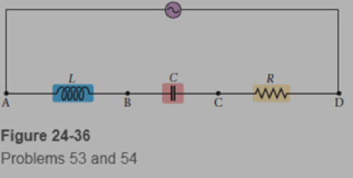
An ac voltmeter, which displays the rms voltage between the two points touched by its leads, is used to measure voltages in the circuit shown in Figure 24-36. In this circuit, the ac generator has an rms voltage of 9 00 V and a frequency of 25 0 kHz. The inductance in the circuit is 0 250 mH, the capacitance is 0 150 ụF, and the resistance is 2 50 Ω What is the reading on a voltmeter when it is connected to points (a) A and B, (b) B and c, (c) A and c, and (d) A and D?

Learn your wayIncludes step-by-step video

Chapter 24 Solutions
Physics (5th Edition)
Additional Science Textbook Solutions
University Physics Volume 2
Conceptual Physical Science (6th Edition)
Essential University Physics: Volume 2 (3rd Edition)
Introduction to Electrodynamics
Physics for Scientists and Engineers: A Strategic Approach, Vol. 1 (Chs 1-21) (4th Edition)
Lecture- Tutorials for Introductory Astronomy


- Write an expression for the output voltage of an ac source that has an amplitude of 12 V and a frequency of 200 Hz.arrow_forwardA 40-mH inductor is connected to a 60-Hz AC source whose voltage amplitude is 50 V. If an AC voltmeter is placed across the inductor, what does it read?arrow_forward(a) At what two times in the first period following t = 0 does the instantaneous voltage in 60-Hz AC equal Vrms ? (b) V rms?arrow_forward
- An AC generator with an rms emf of 15.0 V is connected in series with a 0.54-H inductor. The frequency of the source emf is 70.0 Hz. Draw a phasor diagram for this circuit, including the current, the potential difference across the inductor, and the source emf. Draw your diagram with the current phasor pointing toward the right along the horizontal axis.arrow_forwardThe emf of an ac source is given by v(t)=V0sint, where V0=100V and =200 . Find an expression that represents the output current of the source if it is connected across (a) a 20-pF capacitor, (b) a 20-mH inductor, and (c) a 50 resistor.arrow_forwardConsider the RC high-pass filler circuit shown in Figure P33.53. (a) Find an expression for the ratio of the amplitude of the output volt age to that of the input voltage in terms of R, C, and the AC source frequency . (b) What value does this ratio approach as the frequency decreases toward zero? (c) What value does this ratio approach as the frequency increases without limit?arrow_forward
- In a series RLC circuit with a maximum current of 0.250 A, an AC source with Vmax= 115 V operating at 60.0 Hz is connected to a 325-mH inductor, a 7.50-F capacitor, and a resistor with unknown resistance R. Draw a phasor diagram for this circuit, including the current, the potential difference across each of the circuit elements, and the source emf. Draw your diagram with the current phasor pointing upward along the vertical axis.arrow_forwardFind the reactances of the following capacitors and inductors in ac circuits with the given frequencies in each case: (a) 2-mH inductor with a frequency 60-Hz of the ac circuit; (b) 2-mM Inductor with a frequency 600-Hz of the ac circuit; (C) 20-mM inductor with a frequency 6-Hz of the ac circuit; (d) 20-mM inductor with a frequency 60-Hz of the ac circuit; (e) 2-mF capacitor with a frequency 60-Hz of the ac circuit; and (f) 2-mF capacitor with a frequency 600-Hz of the AC circuit.arrow_forwardA series RLC circuit has resistance R = 50.0 and inductance L. = 0.500 H. (a) Find the circuits capacitance C if the voltage source operates at a frequency of f = 60.0 Hz and the impedance is Z = R = 50.0 . (b) What is the phase angle between the current and the voltage?arrow_forward
- Review. The voltage phasor diagram for a certain series RLC circuit is shown in Figure P33.59. The resistance of the circuit is 75.0 , and the frequency is 60.0 Hz. Find (a) the maximum voltage Vmax, (b) the phase angle , (c) the maximum current, (d) the impedance, (e) the capacitance and (f) the inductance of the circuit, and (g) the average power delivered to the circuit.arrow_forwardIn an oscillating RLC circuit, R = 7.0 L. = 10 mH. And C = 3.0 F. Initially, the capacitor has a charge of 8.0 C and the current is zero. Calculate the charge on the capacitor (a) five cycles later and (b) 50 cycles later.arrow_forwardAn RLC series circuit consists of a 50 resistor, a 200F capacitor, and a 120-mN inductor whose coil has a resistance of 20. The source for the circuit has an tins emf of 240 V at a frequency of 60 Hz. Calculate the tins voltages across the (a) resistor, (b) capacitor, and (c) inductor.arrow_forward
 College PhysicsPhysicsISBN:9781305952300Author:Raymond A. Serway, Chris VuillePublisher:Cengage Learning
 College PhysicsPhysicsISBN:9781285737027Author:Raymond A. Serway, Chris VuillePublisher:Cengage Learning
 Physics for Scientists and Engineers: Foundations...PhysicsISBN:9781133939146Author:Katz, Debora M.Publisher:Cengage Learning
 Glencoe Physics: Principles and Problems, Student...PhysicsISBN:9780078807213Author:Paul W. ZitzewitzPublisher:Glencoe/McGraw-Hill
 Physics for Scientists and Engineers, Technology ...PhysicsISBN:9781305116399Author:Raymond A. Serway, John W. JewettPublisher:Cengage Learning