
Engineering Mechanics: Statics and Study Pack (13th Edition)
13th Edition
ISBN: 9780133027990
Author: Russell C. Hibbeler
Publisher: Prentice Hall
expand_more
expand_more
format_list_bulleted
Videos
Textbook Question
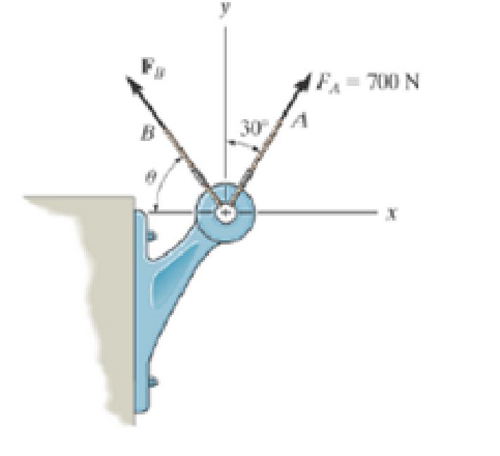
Chapter 2.4, Problem 43P
measured counterclockwise from the positive y axis, of the resultant force acting on the bracket, if FB = 600 N and θ = 20°.
Expert Solution & Answer
Want to see the full answer?
Check out a sample textbook solution
Students have asked these similar questions
CORRECT AND DETAILED SOLUTION WITH FBD ONLY. I WILL UPVOTE THANK YOU. CORRECT ANSWER IS ALREADY PROVIDED. I REALLY NEED FBD.
The cantilevered spandrel beam shown whose depth tapers from d1 to d2, has a constant width of 120mm. It carries a triangularly distributed end reaction.Given: d1 = 600 mm, d2 = 120 mm, L = 1 m, w = 100 kN/m1. Calculate the maximum flexural stress at the support, in kN-m.2. Determine the distance (m), from the free end, of the section with maximum flexural stress.3. Determine the maximum flexural stress in the beam, in MPa.ANSWERS: (1) 4.630 MPa; (2) 905.8688 m; (3) 4.65 MPa
CORRECT AND DETAILED SOLUTION WITH FBD ONLY. I WILL UPVOTE THANK YOU. CORRECT ANSWER IS ALREADY PROVIDED. I REALLY NEED FBD
A concrete wall retains water as shown. Assume that the wall is fixed at the base. Given: H = 3 m, t = 0.5m, Concrete unit weight = 23 kN/m3Unit weight of water = 9.81 kN/m3(Hint: The pressure of water is linearly increasing from the surface to the bottom with intensity 9.81d.)1. Find the maximum compressive stress (MPa) at the base of the wall if the water reaches the top.2. If the maximum compressive stress at the base of the wall is not to exceed 0.40 MPa, what is the maximum allowable depth(m) of the water?3. If the tensile stress at the base is zero, what is the maximum allowable depth (m) of the water?ANSWERS: (1) 1.13 MPa, (2) 2.0 m, (3) 1.20 m
CORRECT AND DETAILED SOLUTION WITH FBD ONLY. I WILL UPVOTE THANK YOU. CORRECT ANSWER IS ALREADY PROVIDED. I NEED FBD
A short plate is attached to the center of the shaft as shown. The bottom of the shaft is fixed to the ground.Given: a = 75 mm, h = 125 mm, D = 38 mmP1 = 24 kN, P2 = 28 kN1. Calculate the maximum torsional stress in the shaft, in MPa.2. Calculate the maximum flexural stress in the shaft, in MPa.3. Calculate the maximum horizontal shear stress in the shaft, in MPa.ANSWERS: (1) 167.07 MPa; (2) 679.77 MPa; (3) 28.22 MPa
Chapter 2 Solutions
Engineering Mechanics: Statics and Study Pack (13th Edition)
Ch. 2.3 - Determine the magnitude of the resultant force...Ch. 2.3 - Determine the magnitude of the resultant force....Ch. 2.3 - Determine the magnitude of the resultant force and...Ch. 2.3 - Resolve the 30-lb force into components along the...Ch. 2.3 - Resolve this force into components acting along...Ch. 2.3 - along the v axis. Prob. F2-6Ch. 2.3 - Determine the magnitude of the resultant force FR...Ch. 2.3 - If = 60 and F = 450 N, determine the magnitude of...Ch. 2.3 - If the magnitude of the resultant force is to be...Ch. 2.3 - Determine the magnitude of the resultant force FR...
Ch. 2.3 - Prob. 5PCh. 2.3 - Prob. 6PCh. 2.3 - Determine the magnitudes of the two components of...Ch. 2.3 - Solve with F = 350 lb. Prob. 2-4/5Ch. 2.3 - Prob. 9PCh. 2.3 - Prob. 10PCh. 2.3 - Resolve this force into two components acting...Ch. 2.3 - Determine the magnitude of F and its component...Ch. 2.3 - Determine the magnitude of F and its direction ....Ch. 2.3 - Prob. 14PCh. 2.3 - If = 60, determine the magnitude of the resultant...Ch. 2.3 - Also, what is the magnitude of the resultant...Ch. 2.3 - What is the component of force acting along member...Ch. 2.3 - Take = 30. Probs. 2-19/20Ch. 2.3 - Determine the magnitude and direction of the...Ch. 2.3 - Determine the magnitude and direction of the...Ch. 2.3 - If F1 = 400 N and F2 = 600 N, determine the angle...Ch. 2.3 - If their lines of action are at an angle apart...Ch. 2.3 - Prob. 23PCh. 2.3 - Prob. 24PCh. 2.3 - Prob. 25PCh. 2.3 - Prob. 26PCh. 2.3 - Prob. 27PCh. 2.3 - directed along the positive x axis, determine the...Ch. 2.3 - If FB = 3 kN and = 45, determine the magnitude of...Ch. 2.3 - If the resultant force of the two tugboats is...Ch. 2.3 - Prob. 31PCh. 2.4 - Resolve each force acting on the post into its x...Ch. 2.4 - Determine the magnitude and direction of the...Ch. 2.4 - Determine the magnitude of the resultant force...Ch. 2.4 - determine the magnitude of F and its direction ....Ch. 2.4 - If the magnitude of the resultant force acting on...Ch. 2.4 - Determine the magnitude of the resultant force and...Ch. 2.4 - Prob. 32PCh. 2.4 - Prob. 33PCh. 2.4 - Resolve F1 and F2 into their x and y components.Ch. 2.4 - Determine the magnitude of the resultant force and...Ch. 2.4 - Resolve each force acting on the gusset plate into...Ch. 2.4 - Determine the magnitude of the resultant force...Ch. 2.4 - Prob. 38PCh. 2.4 - Prob. 39PCh. 2.4 - Prob. 40PCh. 2.4 - Prob. 41PCh. 2.4 - Determine the magnitude and orientation of FB so...Ch. 2.4 - measured counterclockwise from the positive y...Ch. 2.4 - Prob. 44PCh. 2.4 - Prob. 45PCh. 2.4 - Prob. 46PCh. 2.4 - Determine the magnitude and direction of the...Ch. 2.4 - Prob. 48PCh. 2.4 - Prob. 49PCh. 2.4 - Prob. 50PCh. 2.4 - Prob. 51PCh. 2.4 - Prob. 52PCh. 2.4 - What is the magnitude of the resultant force?...Ch. 2.4 - Prob. 54PCh. 2.4 - Prob. 55PCh. 2.4 - Prob. 56PCh. 2.4 - Prob. 57PCh. 2.4 - If the magnitude of the resultant force acting on...Ch. 2.4 - Set = 30. Probs. 2-56/57Ch. 2.6 - Determine the coordinate direction angles of the...Ch. 2.6 - Express the force as a Cartesian vector. Prob....Ch. 2.6 - Express the force as a Cartesian vector. Prob....Ch. 2.6 - Express the force as a Cartesian vector. Prob....Ch. 2.6 - Express the force as a Cartesian vector. Prob....Ch. 2.6 - Determine the resultant force acting on the hook....Ch. 2.6 - Prob. 60PCh. 2.6 - Determine the magnitude and coordinate direction...Ch. 2.6 - Specify the coordinate direction angles of F1 and...Ch. 2.6 - If the magnitude of F is 80 N, and = 60 and =...Ch. 2.6 - Prob. 64PCh. 2.6 - Prob. 65PCh. 2.6 - Prob. 66PCh. 2.6 - Prob. 67PCh. 2.6 - Prob. 68PCh. 2.6 - Prob. 69PCh. 2.6 - Prob. 70PCh. 2.6 - Prob. 71PCh. 2.6 - Prob. 72PCh. 2.6 - Express each force as a Cartesian vector.Ch. 2.6 - Determine the resultant of the two forces and...Ch. 2.6 - Prob. 75PCh. 2.6 - Prob. 76PCh. 2.6 - Prob. 77PCh. 2.6 - Prob. 78PCh. 2.6 - Prob. 79PCh. 2.6 - If the coordinate direction angles for F1 are 3 =...Ch. 2.6 - If the coordinate direction angles for F1 are 3 =...Ch. 2.6 - If the direction of the resultant force acting on...Ch. 2.6 - Express each force in Cartesian vector form and...Ch. 2.6 - Prob. 84PCh. 2.6 - If = 75, determine the magnitudes of F and Fy....Ch. 2.8 - Express the position vector rAB in Cartesian...Ch. 2.8 - What is the angle ? Prob. F2-20Ch. 2.8 - Prob. 21FPCh. 2.8 - Express the force as a Cartesian vector. Prob....Ch. 2.8 - Determine the magnitude of the resultant force at...Ch. 2.8 - Determine the resultant force at A. Prob. F2-24Ch. 2.8 - Prob. 86PCh. 2.8 - Prob. 87PCh. 2.8 - Prob. 88PCh. 2.8 - If F = {350i 250j 450k} N and cable AB is 9 m...Ch. 2.8 - Prob. 90PCh. 2.8 - Prob. 91PCh. 2.8 - If FB = 560 N and FC = 700 N, determine the...Ch. 2.8 - If FB = 700 N, and FC = 560 N, determine the...Ch. 2.8 - Prob. 94PCh. 2.8 - Prob. 95PCh. 2.8 - Prob. 96PCh. 2.8 - Prob. 97PCh. 2.8 - Express this force as a Cartesian vector acting on...Ch. 2.8 - Prob. 99PCh. 2.8 - Prob. 100PCh. 2.8 - Represent each force as a Cartesian vector and...Ch. 2.8 - Prob. 102PCh. 2.8 - If the force in each cable tied to the bin is 70...Ch. 2.8 - Due to symmetry, the tension in the four cables is...Ch. 2.8 - Prob. 105PCh. 2.8 - If the force in each chain has a magnitude of 60...Ch. 2.8 - If the resultant force at O has a magnitude of 130...Ch. 2.8 - Prob. 108PCh. 2.8 - Prob. 109PCh. 2.8 - Prob. 110PCh. 2.8 - Determine the length of the chain, and express the...Ch. 2.9 - Determine the angle between the force and the...Ch. 2.9 - Determine the angle between the force and the...Ch. 2.9 - Determine the angle between the force and the...Ch. 2.9 - Determine the projected component of the force...Ch. 2.9 - Find the magnitude of the projected component of...Ch. 2.9 - Determine the components of the force acting...Ch. 2.9 - Determine the magnitudes of the components of the...Ch. 2.9 - Prob. 112PCh. 2.9 - Determine the angle between the edges of the...Ch. 2.9 - Prob. 114PCh. 2.9 - Prob. 115PCh. 2.9 - Prob. 116PCh. 2.9 - Prob. 117PCh. 2.9 - Determine the projection of the force F along the...Ch. 2.9 - Determine the angle between the y axis of the...Ch. 2.9 - Determine the magnitudes of the components of F =...Ch. 2.9 - Determine the magnitude of the projection of force...Ch. 2.9 - Prob. 122PCh. 2.9 - Prob. 123PCh. 2.9 - Prob. 124PCh. 2.9 - Prob. 125PCh. 2.9 - Determine the magnitude of the projected component...Ch. 2.9 - Determine the angle between the two cables...Ch. 2.9 - Prob. 128PCh. 2.9 - Express this component as a Cartesian vector....Ch. 2.9 - Prob. 130PCh. 2.9 - Determine the angles and made between the axes...Ch. 2.9 - Prob. 132PCh. 2.9 - Prob. 133PCh. 2.9 - Determine the magnitudes of the components of the...Ch. 2.9 - Prob. 135PCh. 2.9 - Express the force F in Cartesian vector form if it...Ch. 2.9 - Express force F in Cartesian vector form if point...Ch. 2.9 - Determine the magnitudes of the projected...Ch. 2.9 - Prob. 139PCh. 2.9 - Prob. 140RPCh. 2.9 - Determine the x and y components of F1 and F2....Ch. 2.9 - Determine the magnitude of the resultant force and...Ch. 2.9 - Determine the magnitude of the resultant force...Ch. 2.9 - Express F1 and F2 as Cartesian vectors.Ch. 2.9 - Determine the magnitude of the resultant force and...Ch. 2.9 - The cable attach to the tractor at B exerts a...Ch. 2.9 - Prob. 147RPCh. 2.9 - Prob. 148RPCh. 2.9 - Prob. 149RP
Knowledge Booster


Learn more about
Need a deep-dive on the concept behind this application? Look no further. Learn more about this topic, mechanical-engineering and related others by exploring similar questions and additional content below.Similar questions
- CORRECT AND DETAILED SOLUTION WITH FBD ONLY. I WILL UPVOTE THANK YOU. CORRECT ANSWER IS ALREADY PROVIDED. I REALLY NEED FBD. The roof truss shown carries roof loads, where P = 10 kN. The truss is consisting of circular arcs top andbottom chords with radii R + h and R, respectively.Given: h = 1.2 m, R = 10 m, s = 2 m.Allowable member stresses:Tension = 250 MPaCompression = 180 MPa1. If member KL has square section, determine the minimum dimension (mm).2. If member KL has circular section, determine the minimum diameter (mm).3. If member GH has circular section, determine the minimum diameter (mm).ANSWERS: (1) 31.73 mm; (2) 35.81 mm; (3) 18.49 mmarrow_forwardPROBLEM 3.23 3.23 Under normal operating condi- tions a motor exerts a torque of magnitude TF at F. The shafts are made of a steel for which the allowable shearing stress is 82 MPa and have diameters of dCDE=24 mm and dFGH = 20 mm. Knowing that rp = 165 mm and rg114 mm, deter- mine the largest torque TF which may be exerted at F. TF F rG- rp B CH TE Earrow_forward1. (16%) (a) If a ductile material fails under pure torsion, please explain the failure mode and describe the observed plane of failure. (b) Suppose a prismatic beam is subjected to equal and opposite couples as shown in Fig. 1. Please sketch the deformation and the stress distribution of the cross section. M M Fig. 1 (c) Describe the definition of the neutral axis. (d) Describe the definition of the modular ratio.arrow_forward
- using the theorem of three moments, find all the moments, I only need concise calculations with minimal explanations. The correct answers are provided at the bottomarrow_forwardMechanics of materialsarrow_forwardusing the theorem of three moments, find all the moments, I need concise calculations onlyarrow_forward
- Can you provide steps and an explaination on how the height value to calculate the Pressure at point B is (-5-3.5) and the solution is 86.4kPa.arrow_forwardPROBLEM 3.46 The solid cylindrical rod BC of length L = 600 mm is attached to the rigid lever AB of length a = 380 mm and to the support at C. When a 500 N force P is applied at A, design specifications require that the displacement of A not exceed 25 mm when a 500 N force P is applied at A For the material indicated determine the required diameter of the rod. Aluminium: Tall = 65 MPa, G = 27 GPa. Aarrow_forwardFind the equivalent mass of the rocker arm assembly with respect to the x coordinate. k₁ mi m2 k₁arrow_forward
arrow_back_ios
SEE MORE QUESTIONS
arrow_forward_ios
Recommended textbooks for you
 International Edition---engineering Mechanics: St...Mechanical EngineeringISBN:9781305501607Author:Andrew Pytel And Jaan KiusalaasPublisher:CENGAGE L
International Edition---engineering Mechanics: St...
Mechanical Engineering
ISBN:9781305501607
Author:Andrew Pytel And Jaan Kiusalaas
Publisher:CENGAGE L
How to balance a see saw using moments example problem; Author: Engineer4Free;https://www.youtube.com/watch?v=d7tX37j-iHU;License: Standard Youtube License