
Delmar's Standard Textbook of Electricity (MindTap Course List)
6th Edition
ISBN: 9781285852706
Author: Stephen L. Herman
Publisher: Cengage Learning
expand_more
expand_more
format_list_bulleted
Concept explainers
Videos
Textbook Question
thumb_up100%
Chapter 24, Problem 1RQ
What is the phase angle relationship of current and the voltage dropped across a pure resistance?
Expert Solution & Answer
To determine
The phase angle relationship of current and voltage dropped across a pure resistance.
Answer to Problem 1RQ
The phase angle between current and voltage in a pure resistance is zero degrees.
Explanation of Solution
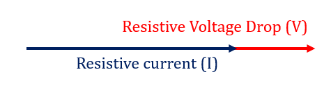
In a pure resistance the current flowing in the resistance is in phase with the voltage drop across it. We say that phase difference between both parameters is zero degrees. The same can be seen in the phasor diagram shown above.
The ohms law for pure resistive circuit is written as,
It can be seen that there is no presence of any imaginary term in the equation above. Hence the phase angle is zero degrees.
Want to see more full solutions like this?
Subscribe now to access step-by-step solutions to millions of textbook problems written by subject matter experts!
Students have asked these similar questions
A plane wave propagating through a medium with ɛ, =
ez/3 sin(108 - Bz)ax V/m. Determine
(a) B
(b) The loss tangent
(c) Intrinsic impedance
(d) Wave velocity
(e) H field
=
8, μ, 2 has
1. Consider the systems whose transfer functions are given as below. Determine (i)
BIBO stability, (ii) strict internal stability, and (iii) marginally internal stability for each
of the systems. You should be able to answer these just simply finding the poles and
checking sign of real part of the poles.
a) H(s) =
(s-3)
(s+1) (s+3)²
2 (s-5)
b) H(s)
=
c) H(s) =
(s-5)(s+1)
$2
((s+3)²+4)2
d) H(s) =
e) H(s) =
S
(s-3)²+4
(S-4)
(s²-4s)(s+1)²
f) H(s) =
S+1
(s²+9)2
should note: it is no coincidence that the inductor current and the
resistor voltage have the same exponential dependence!
PRACTICE
8.5 Determine the inductor voltage v in the circuit of Fig. 8.16 for
t > 0.
Ans: -25e-2t V.
6Ω
ww
4Ω
w
+
t = 0
ν
10 V
ele
ic
5 H
FIGURE 8.16 Circuit for Practice Problem 8.5.
Chapter 24 Solutions
Delmar's Standard Textbook of Electricity (MindTap Course List)
Ch. 24 - What is the phase angle relationship of current...Ch. 24 - What is the phase angle relationship of current...Ch. 24 - What is the phase angle relationship of current...Ch. 24 - An AC circuit has a frequency of 400 Hz. A 16-...Ch. 24 - If 440 V are connected to the circuit, how much...Ch. 24 - Prob. 6RQCh. 24 - What is the true power of the circuit in Question...Ch. 24 - What is the apparent power of the circuit in...Ch. 24 - What is the power factor of the circuit in...Ch. 24 - How many degrees are the voltage and current out...
Ch. 24 - You are an electrician working in a plant. A...Ch. 24 - Prob. 1PPCh. 24 - The circuit is connected to a 400-Hz line with an...Ch. 24 - The circuit is connected to a 60-Hz line. The...Ch. 24 - This circuit is connected to a 1000-Hz line. The...Ch. 24 - A series RLC circuit contains a 4-k resistor, an...Ch. 24 - A series RLC circuit contains a resistor with a...Ch. 24 - Is the power factor in Question 6 a leading or...Ch. 24 - A series RLC circuit contains a resistor with a...Ch. 24 - A series RLC circuit has an applied voltage of 240...Ch. 24 - A series RLC circuit is connected to a 60-Hz power...
Knowledge Booster


Learn more about
Need a deep-dive on the concept behind this application? Look no further. Learn more about this topic, electrical-engineering and related others by exploring similar questions and additional content below.Similar questions
- 3. Determine the range of K for stability of the following feedback control system U(s) + K G(s) →Y(s) where 1 G(s) s(s + 1)(s + 2) To solve this problem, you should first find the closed-loop transfer function and then apply Routh Hurwitz criterion.arrow_forward2. Using Routh Hurwitz criterion, determine the stability of a system whose transfer function is given by the following. 10 H(s) = s5+2s4+3s3+6s²+5s+3arrow_forward4. Consider a unity (negative) feedback control system whose open-loop transfer function is given by the following. 1 G(s): s³ (s + 2) What is the steady state error of the system for input u(t) = t³ 1(t)? Recall from the class lecture that steady-state error is given by the following formula. S ess = lim S-01 + G(s) U(s)arrow_forward
- 5. Answer the following questions. Take help from ChatGPT to answer these questions (if you need). But write the answers briefly using your own words with no more than two sentences and make sure you check whether ChatGPT is giving you the appropriate answers in the context of class. a) What is BIBO stability? b) What is internal stability? What is the difference between strict internal stability and marginal internal stability? c) When is the Routh-Hurwitz criterion especially useful? d) Do the zeros of a transfer function have any impact on stability?arrow_forwardQ+qi R₁ H C₁ h2 Proportional controller qd C₂ R₂ 10+90arrow_forwardI want solution by handwrittenarrow_forward
- in the context of Noise Figure what is the gain in the formula ηs(f) = F*k*T * | H(f) |^2 is always squared? k = Boltzmann constant T = temperature in Kelvin H(f) = gain of the system in questionarrow_forwardA 6-pole, 25-Hz, three-phase, Y-connected, synchronous generator has 36 slots. There are 17 turns per coil, and the flux per pole is 94.8 mWb. Find the line voltage if there are two parallel paths. Sketch the placement of three-phase group coils and show the winding connections. ("arrow_forward072-kVA, 208-V, Y-connected, three-phase synchronous generator delivers the rated load at 0.866 pf lagging. The armature winding resistance is 20 mQ/phase. The core loss is 800 W. The friction and the windage loss is 350 W. The field winding is connected across a 120-V DC source and the field current is 5.5 A. Calculate the efficiency and voltage regulation of the generator.arrow_forward
- 11.32 A Y-D ideal three-phase transformer with a turns ratio of1 : 10 supplies a 32 kVA load at a line voltage of 208 V. Determinethe line voltage and line current at the primary sidearrow_forward11.33 A D-Y ideal three-phase transformer supplies a 32-kVAload at a line voltage of 240 V. If the line voltage at the primaryside is 51.96 V, what is the turns ratio?arrow_forwardI would like assistance with the electrical system of a streetcar/train, specifically in performing calculations related to speed, torque, and power for the motor and the train.Streetcar Gear SystemFrom my research, I have found that streetcars typically do not use traditional gear systems. Instead, the motor directly drives the truck (the assembly that holds the wheels and axles) to achieve the desired speed and torque required by the vehicle. The motor's speed and torque are controlled by a control box, which regulates the motor's performance according to the operational requirements. Truck LimitationsThe truck that will be used has certain limitations, such as: Maximun allowable speed: 50 mph Maximum motor output: 75 hp Motor specification: The specification of the motor is the following:Output power 200 HPSpeed 1150/2000 RPMArm’s voltage 600 VArm’s current 317 AFields volts 220 VField Amps 8/3Field Winding CompoundTorque calculation of the…arrow_forward
arrow_back_ios
SEE MORE QUESTIONS
arrow_forward_ios
Recommended textbooks for you
 Delmar's Standard Textbook Of ElectricityElectrical EngineeringISBN:9781337900348Author:Stephen L. HermanPublisher:Cengage Learning
 Electricity for Refrigeration, Heating, and Air C...Mechanical EngineeringISBN:9781337399128Author:Russell E. SmithPublisher:Cengage Learning
 Power System Analysis and Design (MindTap Course ...Electrical EngineeringISBN:9781305632134Author:J. Duncan Glover, Thomas Overbye, Mulukutla S. SarmaPublisher:Cengage Learning
Delmar's Standard Textbook Of Electricity
Electrical Engineering
ISBN:9781337900348
Author:Stephen L. Herman
Publisher:Cengage Learning
Electricity for Refrigeration, Heating, and Air C...
Mechanical Engineering
ISBN:9781337399128
Author:Russell E. Smith
Publisher:Cengage Learning
Power System Analysis and Design (MindTap Course ...
Electrical Engineering
ISBN:9781305632134
Author:J. Duncan Glover, Thomas Overbye, Mulukutla S. Sarma
Publisher:Cengage Learning
What is a Thyristor? - A Galco TV Tech Tip; Author: GalcoTV;https://www.youtube.com/watch?v=LBb_Qz7J3zA;License: Standard Youtube License