
Mechanics of Materials, Student Value Edition (10th Edition)
10th Edition
ISBN: 9780134321189
Author: Russell C. Hibbeler
Publisher: PEARSON
expand_more
expand_more
format_list_bulleted
Videos
Textbook Question
Chapter 2.2, Problem 2.4PP
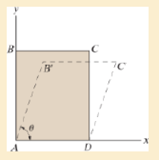
A loading causes the block to deform into the dashed shape. Explain how to determine the strains εAB εAC, εBC, (γA)xy. The angles and distances between all lettered points are known.
P2–4
Expert Solution & Answer

Learn your wayIncludes step-by-step video

schedule03:48
Students have asked these similar questions
CORRECT AND DETAILED SOLUTION WITH FBD ONLY. I WILL UPVOTE THANK YOU. CORRECT ANSWER IS ALREADY PROVIDED. I REALLY NEED FBD.
The cantilevered spandrel beam shown whose depth tapers from d1 to d2, has a constant width of 120mm. It carries a triangularly distributed end reaction.Given: d1 = 600 mm, d2 = 120 mm, L = 1 m, w = 100 kN/m1. Calculate the maximum flexural stress at the support, in kN-m.2. Determine the distance (m), from the free end, of the section with maximum flexural stress.3. Determine the maximum flexural stress in the beam, in MPa.ANSWERS: (1) 4.630 MPa; (2) 905.8688 m; (3) 4.65 MPa
CORRECT AND DETAILED SOLUTION WITH FBD ONLY. I WILL UPVOTE THANK YOU. CORRECT ANSWER IS ALREADY PROVIDED. I REALLY NEED FBD
A concrete wall retains water as shown. Assume that the wall is fixed at the base. Given: H = 3 m, t = 0.5m, Concrete unit weight = 23 kN/m3Unit weight of water = 9.81 kN/m3(Hint: The pressure of water is linearly increasing from the surface to the bottom with intensity 9.81d.)1. Find the maximum compressive stress (MPa) at the base of the wall if the water reaches the top.2. If the maximum compressive stress at the base of the wall is not to exceed 0.40 MPa, what is the maximum allowable depth(m) of the water?3. If the tensile stress at the base is zero, what is the maximum allowable depth (m) of the water?ANSWERS: (1) 1.13 MPa, (2) 2.0 m, (3) 1.20 m
CORRECT AND DETAILED SOLUTION WITH FBD ONLY. I WILL UPVOTE THANK YOU. CORRECT ANSWER IS ALREADY PROVIDED. I NEED FBD
A short plate is attached to the center of the shaft as shown. The bottom of the shaft is fixed to the ground.Given: a = 75 mm, h = 125 mm, D = 38 mmP1 = 24 kN, P2 = 28 kN1. Calculate the maximum torsional stress in the shaft, in MPa.2. Calculate the maximum flexural stress in the shaft, in MPa.3. Calculate the maximum horizontal shear stress in the shaft, in MPa.ANSWERS: (1) 167.07 MPa; (2) 679.77 MPa; (3) 28.22 MPa
Chapter 2 Solutions
Mechanics of Materials, Student Value Edition (10th Edition)
Ch. 2.2 - A loading causes the member to deform into the...Ch. 2.2 - A loading causes the mamber to deform into the...Ch. 2.2 - A loading causes the wires to elongate into the...Ch. 2.2 - A loading causes the block to deform into the...Ch. 2.2 - A loading causes the block to deform into the...Ch. 2.2 - When force P is applied to the rigid arm ABC,...Ch. 2.2 - If the force P causes the rigid arm ABC to rotate...Ch. 2.2 - The rectangular plate is deformed into the shape...Ch. 2.2 - The triangular plate is deformed into the shape...Ch. 2.2 - The square plate is deformed into the shape shown...
Ch. 2.2 - The square deforms into the position shown by the...Ch. 2.2 - The pin-connected rigid rods AB and BC are...Ch. 2.2 - The wire AB is unstretched when = 45. If a load...Ch. 2.2 - If a horizontal load applied to the bar AC causes...Ch. 2.2 - Determine the shear strain xy at corners A and B...Ch. 2.2 - Determine the shear strain xy at corners D and C...Ch. 2.2 - The material distorts into the dashed position...Ch. 2.2 - The material distorts into the dashed position...Ch. 2.2 - Part of a control linkage for an airplane consists...Ch. 2.2 - Part of a control linkage for an airplane consists...Ch. 2.2 - The nylon cord has an original length L and is...Ch. 2.2 - A thin wire, lying along the x axis, is strained...Ch. 2.2 - Determine the shear strain xy at corners A and B...Ch. 2.2 - Determine the shear strain xy at corners D and C...Ch. 2.2 - Determine the average normal strain that occurs...Ch. 2.2 - The corners of the square plate are given the...Ch. 2.2 - The triangular plate is fixed at its base, and its...Ch. 2.2 - The triangular plate is fixed at its base, and its...Ch. 2.2 - The triangular plate is fixed at its base, and its...Ch. 2.2 - The polysulfone block is glued at its top and...Ch. 2.2 - The corners of the square plate are given the...Ch. 2.2 - The corners of the square plate are given the...Ch. 2.2 - The block is deformed into the position shown by...Ch. 2.2 - The rectangular plate is deformed into the shape...Ch. 2.2 - The rectangular plate is deformed into the shape...Ch. 2.2 - The nonuniform loading causes a normal strain in...Ch. 2.2 - The rectangular plate undergoes a deformation...Ch. 2.2 - The fiber AB has a length L and orientation . If...Ch. 2.2 - If the normal strain is defined in reference to...
Additional Engineering Textbook Solutions
Find more solutions based on key concepts
A(n) ____ is a member of a class that holds data. a. method b. instance c. field d. constructor
Starting Out with Programming Logic and Design (5th Edition) (What's New in Computer Science)
The job of the _____ is to fetch instructions, carry out the operations commanded by the instructions, and prod...
Starting Out With Visual Basic (8th Edition)
Fill in the blanks in each of the following statements: A relation that has no partial functional dependencies ...
Modern Database Management
Write an if-else statement that assigns 0 to the variable b if the variable a is less than 10. Otherwise, it sh...
Starting Out with Python (4th Edition)
Assume a telephone signal travels through a cable at two-thirds the speed of light. How long does it take the s...
Electric Circuits. (11th Edition)
In Exercises 41 through 46, identify the errors. Dima,b,c,dAsDoublea=2b=3c=d=4Istoutput.Items.Add(5((a+b)/(c+d)
Introduction To Programming Using Visual Basic (11th Edition)
Knowledge Booster


Learn more about
Need a deep-dive on the concept behind this application? Look no further. Learn more about this topic, mechanical-engineering and related others by exploring similar questions and additional content below.Similar questions
- CORRECT AND DETAILED SOLUTION WITH FBD ONLY. I WILL UPVOTE THANK YOU. CORRECT ANSWER IS ALREADY PROVIDED. I REALLY NEED FBD. The roof truss shown carries roof loads, where P = 10 kN. The truss is consisting of circular arcs top andbottom chords with radii R + h and R, respectively.Given: h = 1.2 m, R = 10 m, s = 2 m.Allowable member stresses:Tension = 250 MPaCompression = 180 MPa1. If member KL has square section, determine the minimum dimension (mm).2. If member KL has circular section, determine the minimum diameter (mm).3. If member GH has circular section, determine the minimum diameter (mm).ANSWERS: (1) 31.73 mm; (2) 35.81 mm; (3) 18.49 mmarrow_forwardPROBLEM 3.23 3.23 Under normal operating condi- tions a motor exerts a torque of magnitude TF at F. The shafts are made of a steel for which the allowable shearing stress is 82 MPa and have diameters of dCDE=24 mm and dFGH = 20 mm. Knowing that rp = 165 mm and rg114 mm, deter- mine the largest torque TF which may be exerted at F. TF F rG- rp B CH TE Earrow_forward1. (16%) (a) If a ductile material fails under pure torsion, please explain the failure mode and describe the observed plane of failure. (b) Suppose a prismatic beam is subjected to equal and opposite couples as shown in Fig. 1. Please sketch the deformation and the stress distribution of the cross section. M M Fig. 1 (c) Describe the definition of the neutral axis. (d) Describe the definition of the modular ratio.arrow_forward
- using the theorem of three moments, find all the moments, I only need concise calculations with minimal explanations. The correct answers are provided at the bottomarrow_forwardMechanics of materialsarrow_forwardusing the theorem of three moments, find all the moments, I need concise calculations onlyarrow_forward
- Can you provide steps and an explaination on how the height value to calculate the Pressure at point B is (-5-3.5) and the solution is 86.4kPa.arrow_forwardPROBLEM 3.46 The solid cylindrical rod BC of length L = 600 mm is attached to the rigid lever AB of length a = 380 mm and to the support at C. When a 500 N force P is applied at A, design specifications require that the displacement of A not exceed 25 mm when a 500 N force P is applied at A For the material indicated determine the required diameter of the rod. Aluminium: Tall = 65 MPa, G = 27 GPa. Aarrow_forwardFind the equivalent mass of the rocker arm assembly with respect to the x coordinate. k₁ mi m2 k₁arrow_forward
arrow_back_ios
SEE MORE QUESTIONS
arrow_forward_ios
Recommended textbooks for you
 Elements Of ElectromagneticsMechanical EngineeringISBN:9780190698614Author:Sadiku, Matthew N. O.Publisher:Oxford University Press
 Mechanics of Materials (10th Edition)Mechanical EngineeringISBN:9780134319650Author:Russell C. HibbelerPublisher:PEARSON
 Thermodynamics: An Engineering ApproachMechanical EngineeringISBN:9781259822674Author:Yunus A. Cengel Dr., Michael A. BolesPublisher:McGraw-Hill Education
 Control Systems EngineeringMechanical EngineeringISBN:9781118170519Author:Norman S. NisePublisher:WILEY
 Mechanics of Materials (MindTap Course List)Mechanical EngineeringISBN:9781337093347Author:Barry J. Goodno, James M. GerePublisher:Cengage Learning
 Engineering Mechanics: StaticsMechanical EngineeringISBN:9781118807330Author:James L. Meriam, L. G. Kraige, J. N. BoltonPublisher:WILEY
Elements Of Electromagnetics
Mechanical Engineering
ISBN:9780190698614
Author:Sadiku, Matthew N. O.
Publisher:Oxford University Press
Mechanics of Materials (10th Edition)
Mechanical Engineering
ISBN:9780134319650
Author:Russell C. Hibbeler
Publisher:PEARSON
Thermodynamics: An Engineering Approach
Mechanical Engineering
ISBN:9781259822674
Author:Yunus A. Cengel Dr., Michael A. Boles
Publisher:McGraw-Hill Education
Control Systems Engineering
Mechanical Engineering
ISBN:9781118170519
Author:Norman S. Nise
Publisher:WILEY
Mechanics of Materials (MindTap Course List)
Mechanical Engineering
ISBN:9781337093347
Author:Barry J. Goodno, James M. Gere
Publisher:Cengage Learning
Engineering Mechanics: Statics
Mechanical Engineering
ISBN:9781118807330
Author:James L. Meriam, L. G. Kraige, J. N. Bolton
Publisher:WILEY
Lec21, Part 5, Strain transformation; Author: Mechanics of Materials (Libre);https://www.youtube.com/watch?v=sgJvz5j_ubM;License: Standard Youtube License