
Concept explainers
Videos
List the five joint types used in welding.
The five types of joints in welding.
Explanation of Solution
Welding joints are of five types:
- Butt joint
- Lap joint
- Tee joints
- Outline corner joint
- Edge joint
Butt joint:
It is a type of welding in which the edges are welded. This do not increase the width of the metal. It has flexibility of being welded from both sides. Edges of metal are kept parallel for welding.
Lap joint:
In this welding, edges of the metal are overlapped to perform the welding operations. A fillet weld is used for performing lap joint. Welds can be performed on either side of the metal pieces.
Tee joints:
In this welding, the surface of one metal is placed over the surface of other metal. The angle between the parts to be welded is right angle. This welding is done by fillet welding.
Outline corner joint:
In this welding, a piece of metal is brought in contact by making an angle of 90-degree. Corners of edged are put together for welding.
Edge joint:
Even edges of two metals are put together by side to perform welding. These joints can be welded from one side only.
Types of welding can be seen in given figure.
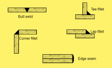
Fig: types of weld joints
Want to see more full solutions like this?
Chapter 22 Solutions
EBK 3I-EBK: WELDING PRINCIPLES & APPLIC


- A 2.5-m-long thin vertical plate is subjected to uniform heat flux on one side, while the other side is exposed to cool air at 5°C. The plate surface has an emissivity of 0.73, and its midpoint temperature is 55°C. Determine the heat flux subjected on the plate surface. Uniform heat flux -Plate, € = 0.73 Cool air 5°C 7 TSUIT Given: The properties of water at Tf,c= 30°C. k=0.02588 W/m.K, v=1.608 x 10⁻⁵ m²/s Pr = 0.7282 The heat flux subjected on the plate surface is W/m²arrow_forwardHot water is flowing at an average velocity of 5.82 ft/s through a cast iron pipe (k=30 Btu/h-ft-°F) whose inner and outer diameters are 1.0 in and 1.2 in, respectively. The pipe passes through a 50-ft-long section of a basement whose temperature is 60°F. The emissivity of the outer surface of the pipe is 0.5, and the walls of the basement are also at about 60°F. If the inlet temperature of the water is 150°F and the heat transfer coefficient on the inner surface of the pipe is 30 Btu/h-ft².°F, determine the temperature drop of water as it passes through the basement. Evaluate air properties at a film temperature of 105°C and 1 atm pressure. The properties of air at 1 atm and the film temperature of (Ts+ T∞)/2 = (150+60)/2 = 105°F are k=0.01541 Btu/h-ft-°F. v=0.1838 × 10⁻³ ft2/s, Pr = 0.7253, and ẞ = 0.00177R-1arrow_forwardhand-written solutions only, please. correct answers upvoted!arrow_forward
- hand-written solutions only, please. correct answers upvoted!arrow_forward! Required information Consider a flat-plate solar collector placed horizontally on the flat roof of a house. The collector is 1.3 m wide and 2.8 m long, and the average temperature of the exposed surface of the collector is 42°C. The properties of air at 1 atm and the film temperature are k=0.02551 W/m-°C, v = 1.562 × 10⁻⁵ m²/s, Pr = 0.7286, and ẞ= 0.003356 K-1 Determine the rate of heat loss from the collector by natural convection during a calm day when the ambient air temperature is 8°C. The rate of heat loss from the collector by natural convection is W.arrow_forwardhand-written solutions only, please. correct answers upvoted!arrow_forward
 Welding: Principles and Applications (MindTap Cou...Mechanical EngineeringISBN:9781305494695Author:Larry JeffusPublisher:Cengage Learning