Videos
(a)
The reactance of the capacitor and the inductor.
(a)
Answer to Problem 93P
The reactance of the capacitor is
Explanation of Solution
Write an expression for the capacitive reactance.
Here,
Write an expression for the inductive reactance.
Here,
Conclusion:
Substitute
Substitute
Thus, the reactance of the capacitor is
(b)
The impedance.
(b)
Answer to Problem 93P
The impedance is
Explanation of Solution
Write an expression for the impedance.
Here,
Conclusion:
Substitute
Thus, the impedance is
(c)
The rms current.
(c)
Answer to Problem 93P
The rms current is
Explanation of Solution
Write an expression for the rms current.
Here,
Conclusion:
Substitute
Thus, the rms current is
(d)
The current amplitude.
(d)
Answer to Problem 93P
The current amplitude is
Explanation of Solution
Write an expression for the current amplitude.
Here,
Conclusion:
Substitute
Thus, the current amplitude is
(e)
The phase angle.
(e)
Answer to Problem 93P
The phase angle is
Explanation of Solution
Write an expression for the phase angle.
Here,
Conclusion:
Substitute
Thus, the phase angle is
(f)
The rms voltage across each of the circuit elements.
(f)
Answer to Problem 93P
The rms voltage across the resistance is
Explanation of Solution
Write an expression for the rms voltage across the resistance.
Here,
Write an expression for the rms voltage across the inductor.
Here,
Write an expression for the rms voltage across the capacitor.
Here,
Conclusion:
Substitute
Substitute
Substitute
Thus, the rms voltage across the resistance is
(g)
If the current leads or lags the voltage.
(g)
Answer to Problem 93P
The current lags the voltage.
Explanation of Solution
From the values of the capacitive reactance and inductive reactance, the inductive reactance is greater than the capacitive reactance.
Conclusion:
As the dominant element is the inductor, the current lags the voltage.
Thus, the current lags the voltage.
(h)
Sketch the phasor diagram.
(h)
Answer to Problem 93P
The phasor diagram is shown in figure 1.
Explanation of Solution
The voltages of the different circuit elements found in part (f) is used to draw the phasor diagram.
The rms voltage across the resistance
The rms voltage across the inductor
The rms voltage across the capacitor
As the dominant element is the inductor, the current lags the voltage.
Conclusion:
The difference between the voltage across the inductor and the voltage across the capacitor is zero.
Sketch the phasor diagram.
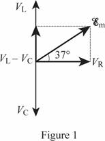
Thus, the phasor diagram is shown in figure 1.
Want to see more full solutions like this?
Chapter 21 Solutions
Physics


- Suppose you have a diverging lens with a focal length of - 25 cm. You look through this lens at a sleeping squirrel, and notice that it forms a virtual image of the squirrel with di = - 18 cm. How far away from the lens is the squirrel? Give your answer as the number of centimeters (a positive number).arrow_forwardDiamond has an index of refraction of about 2.4. Suppose you cut a diamond so it has a flat surface, and shine a laser pointer beam so that it makes a 27 degree angle with respect to the normal line to that surface. What angle will the laser beam make with respect to the normal after it passes through the air-diamond boundary and is inside the diamond? Give your answer as the number of degrees.arrow_forwardFind current of each line of D,E, and F. Where V1 is 9V, V2 is 7V, R1 is 989 , R2 is 2160, R3 is 4630 , R4 is 5530, R5 is 6720, and E is 16V. Please explain all steps. Thank youarrow_forward
- You are tasked with designing a parallel-plate capacitor using two square metal plates, eachwith an area of 0.5 m², separated by a 0.1 mm thick layer of air. However, to increase the capacitance,you decide to insert a dielectric material with a dielectric constant κ = 3.0 between the plates. Describewhat happens (and why) to the E field between the plates when the dielectric is added in place of theair.arrow_forwardCalculate the work required to assemble a uniform charge Q on a thin spherical shell of radiusR. Start with no charge and add infinitesimal charges dq until the total charge reaches Q, assuming thecharge is always evenly distributed over the shell’s surface. Show all steps.arrow_forwardRod AB is fixed to a smooth collar D, which slides freely along the vertical guide shown in (Figure 1). Point C is located just to the left of the concentrated load P = 70 lb. Suppose that w= 17 lb/ft. Follow the sign convention. Part A Figure 3 ft -1.5 ft √30° 1 of 1 Determine the normal force at point C. Express your answer in pounds to three significant figures. ΜΕ ΑΣΦ Η vec Nc= Submit Request Answer Part B Determine the shear force at point C. Express your answer in pounds to three significant figures. VC= ΜΕ ΑΣΦΗ vec Submit Request Answer Part C Determine the moment at point C. Express your answer in pound-feet to three significant figures. Mc= Ο ΑΣΦ Η vec Submit Request Answer Provide Feedback ? ? lb lb ? lb-ftarrow_forward
- Consider a uniformly charged ring of radius R with total charge Q, centered at the origin inthe xy-plane. Find the electric field (as a vector) at a point on the z-axis at a distance z above thecenter of the ring. Assume the charge density is constant along the ring.arrow_forward3) If the slider block C is moving at 3m/s, determine the angular velocity of BC and the crank AB at the instant shown. (Use equation Vs Vc wx fuc, then use equation Vs VA + Ve/athen write it in terms of w and the appropriate r equate the two and solve) 0.5 m B 1 m 60° A 45° vc = 3 m/sarrow_forward3) If the slider block C is moving at 3m/s, determine the angular velocity of BC and the crank AB at the instant shown. (Use equation Vs Vc wxf, then use equation V, VA + Va/Athen write it in terms of w and the appropriate r equate the two and solve) f-3marrow_forward
- Pls help ASAParrow_forwardPls help ASAParrow_forward14. A boy is out walking his dog. From his house, he walks 30 m North, then 23 m East, then 120 cm South, then 95 m West, and finally 10 m East. Draw a diagram showing the path that the boy walked, his total displacement, and then determine the magnitude and direction of his total displacement.arrow_forward
 College PhysicsPhysicsISBN:9781305952300Author:Raymond A. Serway, Chris VuillePublisher:Cengage Learning
 University Physics (14th Edition)PhysicsISBN:9780133969290Author:Hugh D. Young, Roger A. FreedmanPublisher:PEARSON
 Introduction To Quantum MechanicsPhysicsISBN:9781107189638Author:Griffiths, David J., Schroeter, Darrell F.Publisher:Cambridge University Press
 Physics for Scientists and EngineersPhysicsISBN:9781337553278Author:Raymond A. Serway, John W. JewettPublisher:Cengage Learning
 Lecture- Tutorials for Introductory AstronomyPhysicsISBN:9780321820464Author:Edward E. Prather, Tim P. Slater, Jeff P. Adams, Gina BrissendenPublisher:Addison-Wesley
 College Physics: A Strategic Approach (4th Editio...PhysicsISBN:9780134609034Author:Randall D. Knight (Professor Emeritus), Brian Jones, Stuart FieldPublisher:PEARSON