(a)
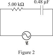
The voltage amplitude across the capacitor and resistor.
(a)
Answer to Problem 44P
The voltage amplitude across the capacitor is
Explanation of Solution
The figure 2 shows the

Write the expression for current generated in an ac source.
Here,
Write the expression for impedance
Here,
Write the expression for capacitive reactance.
Here,
The expression for frequency of the ac source is.
Here,
Conclusion:
Substitute the equation (II) and (III) in equation (I).
Substitute equation (IV) in the equation (V).
Substitute
Write the equation for the voltage across the capacitor.
Substitute the equation (III) and (IV) in the equation (VI).
Substitute
Write the equation for the voltage across the resistor.
Substitute
Therefore, the voltage across the capacitor is
(b)
If the amplitude of voltage and source voltage add together gives
(b)
Answer to Problem 44P
No, the amplitude of voltage do not add to give the source voltage.
Explanation of Solution
Since the voltage amplitude do not add as scalars to give the amplitude of the source voltage because the voltage across the resistor and capacitor are
Conclusion:
Thus, the amplitude of voltage does not give the source voltage by adding as scalars of voltage across the resistance and capacitors.
(c)
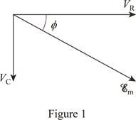
Draw the phasor diagram for the voltages.
(c)
Answer to Problem 44P
The phasor diagram is drawn for the voltage across the resistance and capacitors.
Explanation of Solution
The phasor diagram is used to show the phase relationship between two or more sine waves having the same frequency. The voltage phasor diagram is drawn across the series RLC circuit such as voltage across resistor, voltage across inductor, and voltage across capacitor.
The figure 1 shows the phasor diagram.

Want to see more full solutions like this?
Chapter 21 Solutions
PHYSICS
- An electromagnetic wave is traveling through vacuum in the positive x direction. Its electric field vector is given by E=E0sin(kx−ωt)j^,where j^ is the unit vector in the y direction. If B0 is the amplitude of the magnetic field vector, find the complete expression for the magnetic field vector B→ of the wave. What is the Poynting vector S(x,t), that is, the power per unit area associated with the electromagnetic wave described in the problem introduction? Give your answer in terms of some or all of the variables E0, B0, k, x, ω, t, and μ0. Specify the direction of the Poynting vector using the unit vectors i^, j^, and k^ as appropriate. Please explain all stepsarrow_forwardAnother worker is performing a task with an RWL of only 9 kg and is lifting 18 kg, giving him an LI of 2.0 (high risk). Questions:What is the primary issue according to NIOSH?Name two factors of the RWL that could be improved to reduce risk.If the horizontal distance is reduced from 50 cm to 30 cm, how does the HM change and what effect would it have?arrow_forwardTwo complex values are z1=8 + 8i, z2=15 + 7 i. z1∗ and z2∗ are the complex conjugate values. Any complex value can be expessed in the form of a+bi=reiθ. Find r and θ for z1z2∗. Find r and θ for z1/z2∗? Find r and θ for (z1−z2)∗/z1+z2∗. Find r and θ for (z1−z2)∗/z1z2∗ Please explain all steps, Thank youarrow_forward
- An ac series circuit consists of a voltage source of frequency 60 Hz and voltage amplitude V, a 505-Ω resistor, and a capacitor of capacitance 7.2 μF. What must be the source voltage amplitude V for the average electrical power consumed in the resistor to be 236 W? There is no inductance in the circuit.arrow_forwardAn L−R−C series circuit has R= 280 Ω . At the frequency of the source, the inductor has reactance XLL= 905 Ω and the capacitor has reactance XC= 485 Ω . The amplitude of the voltage across the inductor is 445 V . What is the amplitude of the voltage across the resistor and the capacitor? What is the voltage amplitude of the source? What is the rate at which the source is delivering electrical energy to the circuit?arrow_forwardA 0.185 H inductor is connected in series with a 98.5 Ω resistor and an ac source. The voltage across the inductor is vL=−(12.5V)sin[(476rad/s)t]vL. Derive an expression for the voltage vR across the resistor. Express your answer in terms of the variables L, R, VL (amplitude of the voltage across the inductor), ω, and t. What is vR at 2.13 ms ? Please explain all stepsarrow_forward
- A worker lifts a box under the following conditions:Horizontal distance (H): 30 cmInitial height (V): 60 cmVertical travel (D): 50 cmTorso rotation (A): 30°Frequency: 3 times/minute for 1 hourGrip: Good Question:What is the RWL for this task?What does this value mean in terms of occupational safety?arrow_forwardCan someone helparrow_forwardCan someone help mearrow_forward
- 3. Four identical small masses are connected in a flat perfect square. Rank the relative rotational inertias (IA, IB, IC) about the three axes of rotation shown. Axes A and B are in the plane of the square, and axis C is perpendicular to the plane, through mass m1. ΙΑ IB m2 m1 m3 Ic m4 (a) IAarrow_forwardConsider the circuit shown in the figure below. (Assume L = 5.20 m and R2 = 440 Ω.) (a) When the switch is in position a, for what value of R1 will the circuit have a time constant of 15.4 µs? (b) What is the current in the inductor at the instant the switch is thrown to position b?arrow_forwardCan someone helparrow_forwardarrow_back_iosSEE MORE QUESTIONSarrow_forward_ios
 College PhysicsPhysicsISBN:9781305952300Author:Raymond A. Serway, Chris VuillePublisher:Cengage Learning
 University Physics (14th Edition)PhysicsISBN:9780133969290Author:Hugh D. Young, Roger A. FreedmanPublisher:PEARSON
 Introduction To Quantum MechanicsPhysicsISBN:9781107189638Author:Griffiths, David J., Schroeter, Darrell F.Publisher:Cambridge University Press
 Physics for Scientists and EngineersPhysicsISBN:9781337553278Author:Raymond A. Serway, John W. JewettPublisher:Cengage Learning
 Lecture- Tutorials for Introductory AstronomyPhysicsISBN:9780321820464Author:Edward E. Prather, Tim P. Slater, Jeff P. Adams, Gina BrissendenPublisher:Addison-Wesley
 College Physics: A Strategic Approach (4th Editio...PhysicsISBN:9780134609034Author:Randall D. Knight (Professor Emeritus), Brian Jones, Stuart FieldPublisher:PEARSON


