Fundamentals of Building Construction
6th Edition
ISBN: 9781118138915
Author: Edward Allen
Publisher: WILEY
expand_more
expand_more
format_list_bulleted
Concept explainers
Question
Chapter 20, Problem 1RQ
To determine
Write about the common ways of attaching stone cladding attachment with simple sketches and describe each system.
Expert Solution & Answer
Explanation of Solution
Stone cladding attachment:
Stone panels mounted on a steel sub frame:
Draw the free body diagram of steel sub frame with stone panels as in Figure (1).
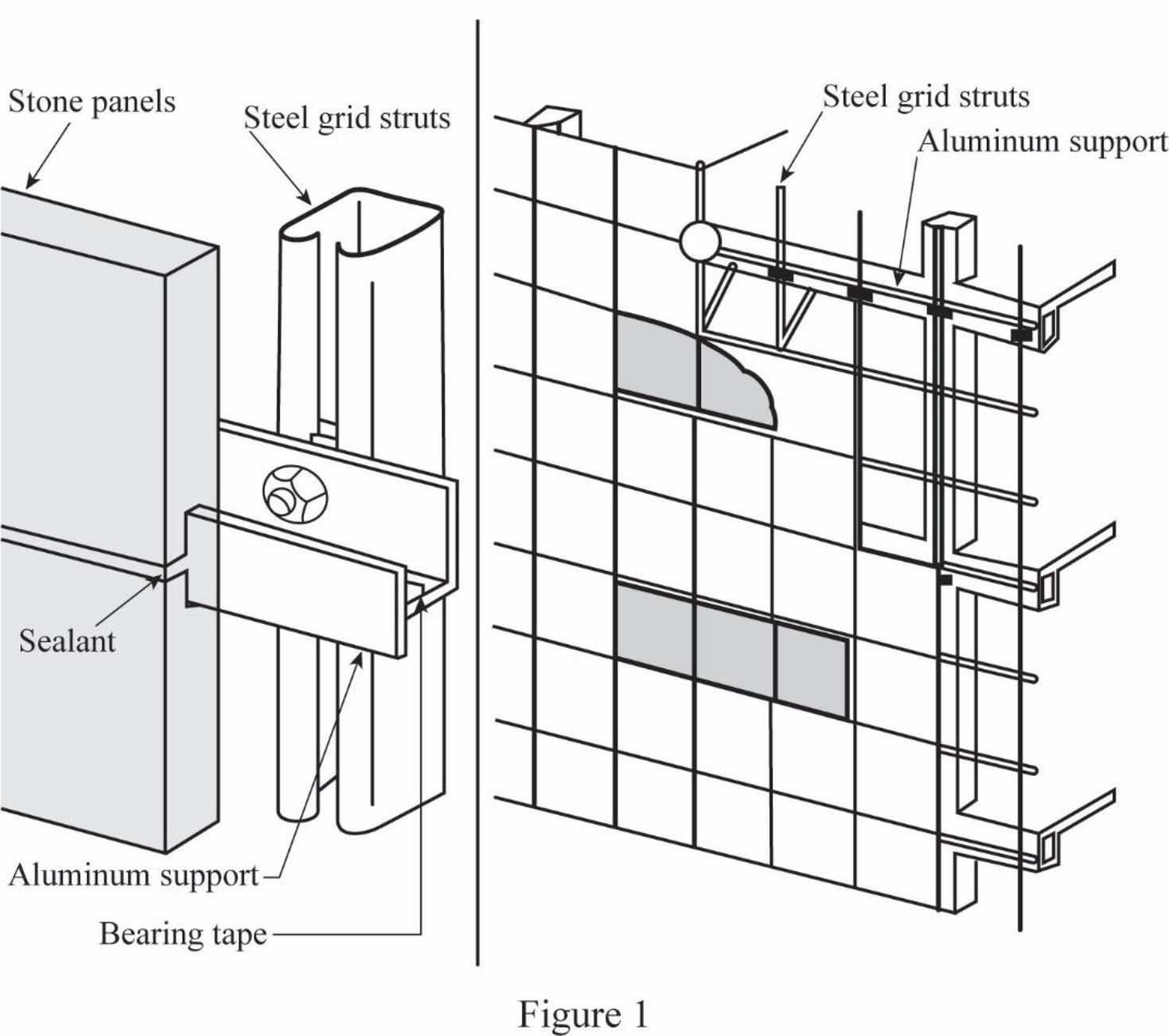
- Initially, the vertical members are erected to transfer wind and gravity loads. Aluminum-support horizontal members are engaged in slots in lower and upper edges of the each stone.
- The joint between the stones are filled by the sealants and backer rods. Air barrier, insulation, interior finishes, and electrical wiring are provided by the construction of non-structural steel stud back-up wall and gypsum sheathing within the building frame.
- Sealant joints are the weak link for penetration of water.
Monolithic stone cladding panels:
Draw the free body diagram of monolithic stone cladding panels as in Figure (2).
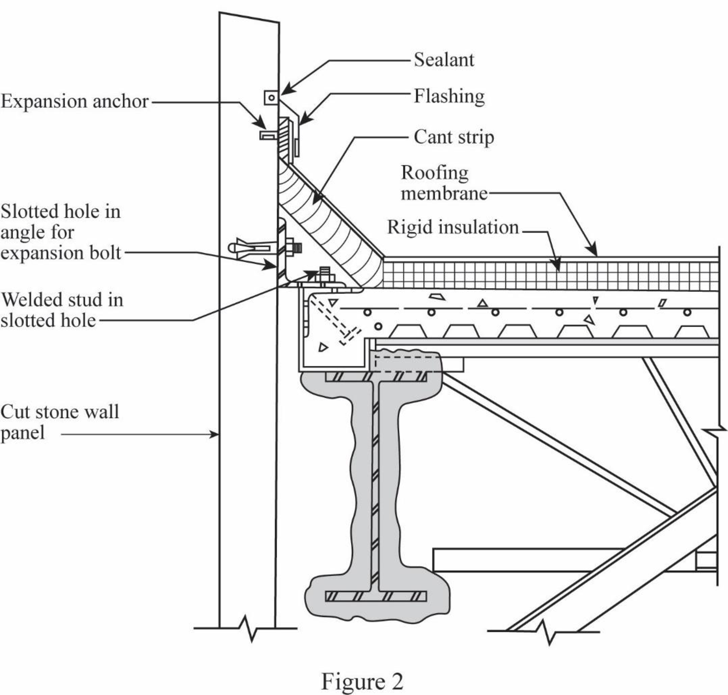
- The fitting of panel is done to the building frame directly, and each panel weight is conveyed to two steel support plates using edge pockets that are cut into both sides of each panel at the stone mill.
- Steel angle strut pair is used to stabilize each panel that is bolted to the stone, using expansion anchors in drilled holes.
- Backer rod and sealant are used to close the joints and a nonstructural backup wall is needed.
Stone cladding on steel trusses:
Draw the free body diagram of truss-supported stone cladding as in Figure (3).
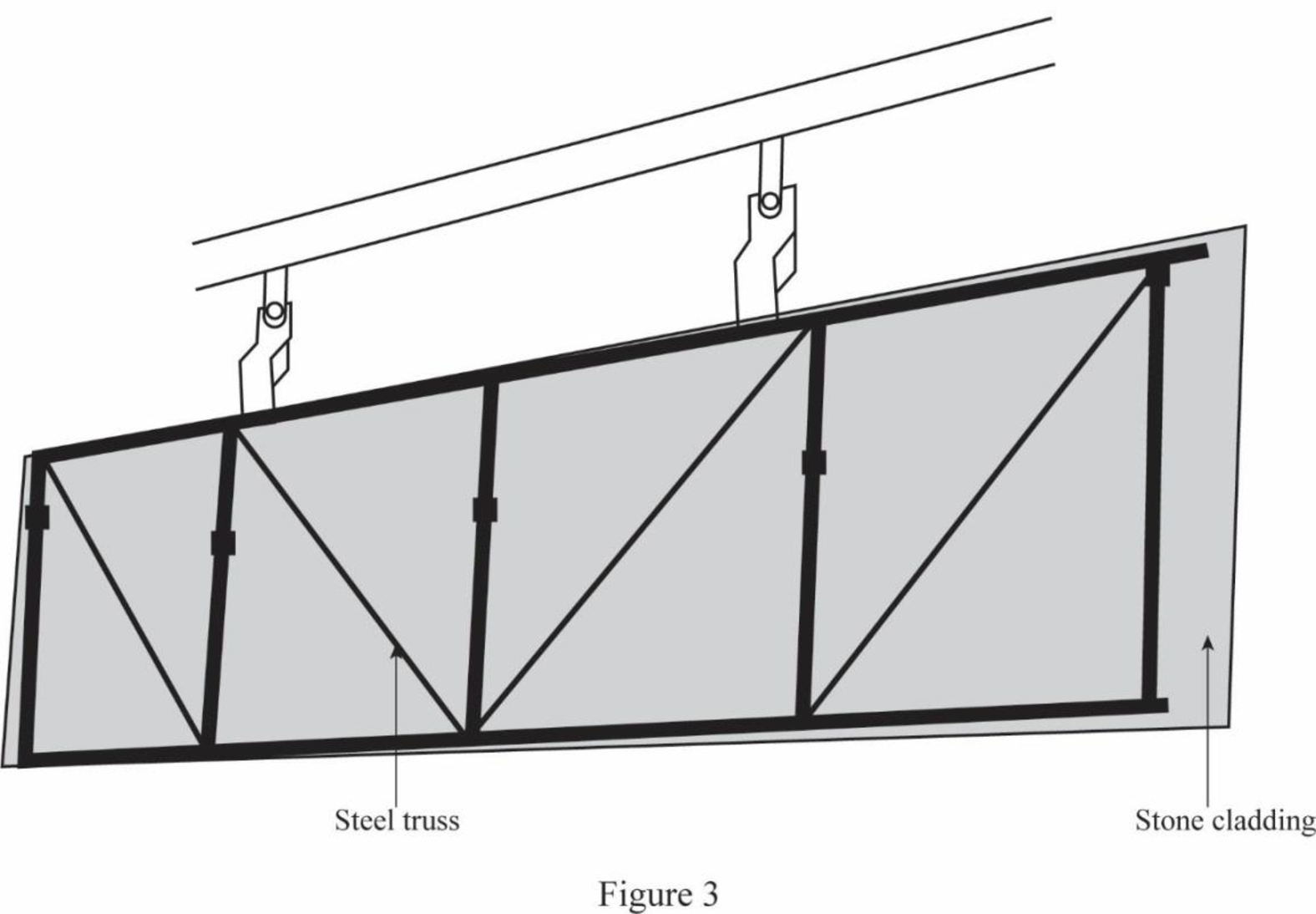
- In this system, stone sheets are joined into large prefabricated panels by escalating them on steel trusses.
- The design of each truss is done in such a way that it carries both wind loads and dead load of the stone to link brackets that convey these loads to the building frame.
- Sealant joints and non-structural backup wall complete the installation.
Posttensioned limestone spandrel panels:
Draw the free body diagram of spandrel panels as in Figure (4).
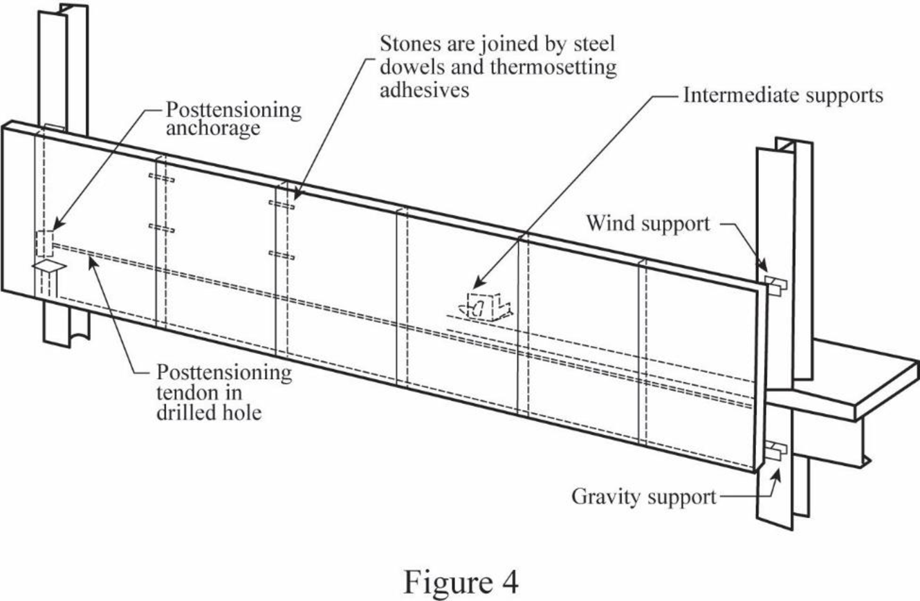
- Thick limestone blocks may be combined with adhesives into long spandrel panels, and high-strength steel tendons are used for posttensioned, so that the assembly is self-supporting between columns.
- This method is relatively very costly due to the usage of moderately large amounts of stone per unit cladding area.
Very thin stone facings:
Draw the free body diagram of thin stone facings as in Figure (5).
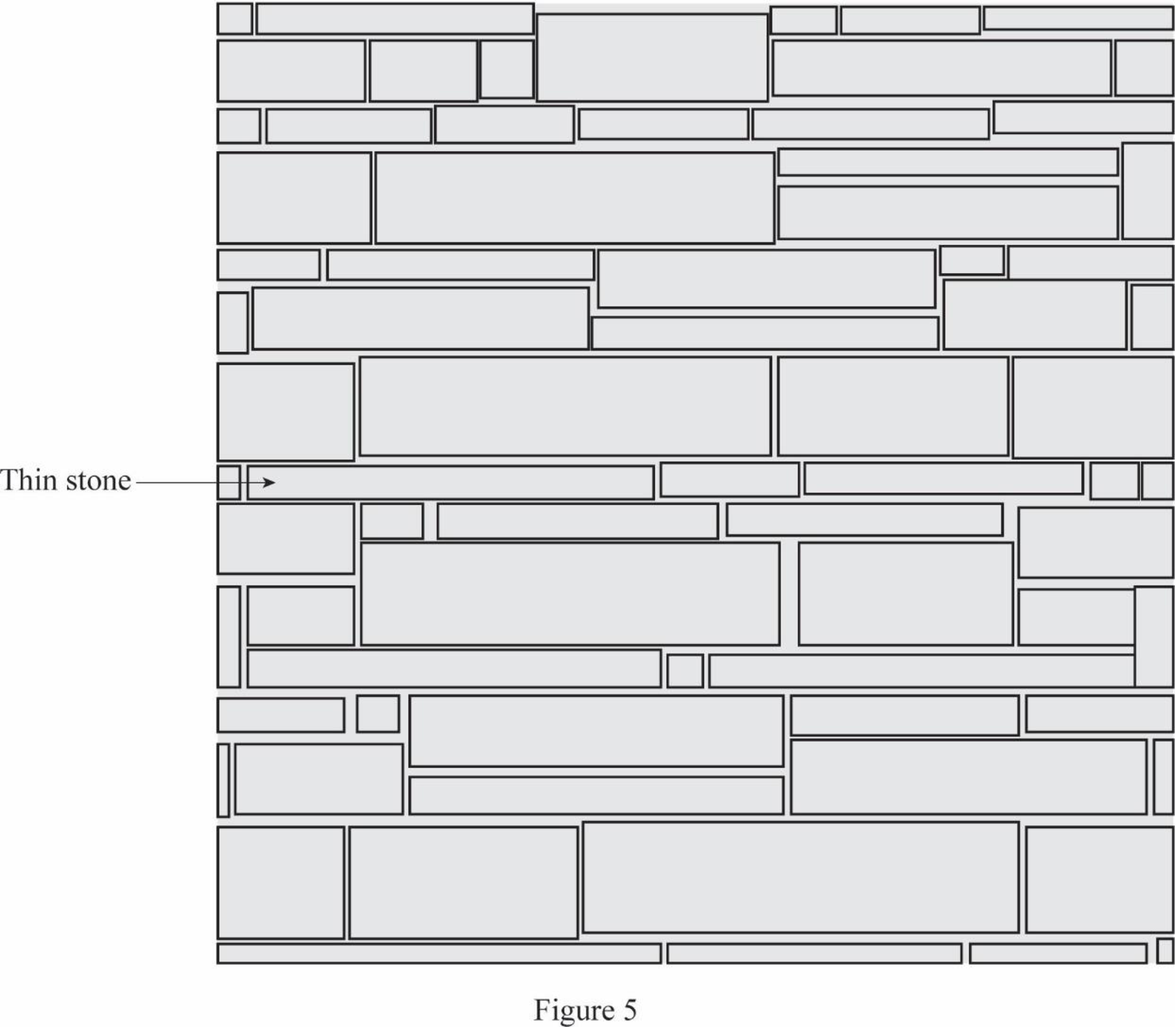
- Extremely thin stone sheets may be stiffened with a structural backing, such as a metal honeycomb, and escalated as spandrel panels in an aluminum mullion system.
- Very thin stone sheets may be applied as facings for precast concrete curtain wall panels.
- Thin stones are a result of the number of failures of cladding systems.
Want to see more full solutions like this?
Subscribe now to access step-by-step solutions to millions of textbook problems written by subject matter experts!
Students have asked these similar questions
instructions: make sure to follow the
instructions and provide complete and
detailed solution
create/draw a beam with uniformly
distributed load and concentrated load
after, find the shear and moment
equation
and ensure to draw it's shear and
moment diagram
once done, write it's conclusion or
observation
4:57 PM
Solve for forces on pin C and D
Borrow pit soil is being used to fill an 900,00 yd3 of depression. The properties of borrowpit and in-place fill soils obtained from laboratory test results are as follows:• Borrow pit soil: bulk density 105 pcf, moisture content = 8%, and specific gravity = 2.65• In-place fill soil: dry unit weight =120 pcf, and moisture content = 16%(a) How many yd3 of borrow soil is required?(b) What water mass is needed to achieve 16% moisture in the fill soil?(c) What is the in-place density after a long rain?
Chapter 20 Solutions
Fundamentals of Building Construction
Knowledge Booster


Learn more about
Need a deep-dive on the concept behind this application? Look no further. Learn more about this topic, civil-engineering and related others by exploring similar questions and additional content below.Similar questions
- solve for dt/dx=f(t,x)=x+t^2arrow_forwardCalculate the BMs (bending moments) at all the joints of the beam shown in Fig.1 using the slope deflection method, draw the resulting shear force diagran and bending moment diagram. The beam is subjected to an UDL of w=65m. L=4.5m, L1= 1.8m. Assume the support at C is pinned, and A and B are roller supports. E = 200 GPa, I = 250x106 mm4.arrow_forwardProblem 2 (A is fixed and C is a pin) Find the reactions and A and C. 10 k- 6 ft 6 ft B A 2 k/ft 15 ftarrow_forward
- 6. A lake with no outlet is fed by a river with a constant flow of 1200 ft3/s. Water evaporates from the surface at a constant rate of 13 ft3/s per square mile of surface area. The surface area varies with the depth h (in feet) as A (square miles) = 4.5 + 5.5h. What is the equilibrium depth of the lake? Below what river discharge (volume flow rate) will the lake dry up?arrow_forwardProblem 5 (A, B, C and D are fixed). Find the reactions at A and D 8 k B 15 ft A -20 ft C 10 ft Darrow_forwardProblem 4 (A, B, E, D and F are all pin connected and C is fixed) Find the reactions at A, D and F 8 m B 6m E 12 kN D F 4 marrow_forward
- Problem 1 (A, C and D are pins) Find the reactions and A, C and D. D 6 m B 12 kN/m 8 m A C 6 marrow_forwardUniform Grade of Pipe Station of Point A is 9+50.00. Elevation Point A = 250.75.Station of Point B is 13+75.00. Elevation Point B = 244.10 1) Calculate flowline of pipe elevations at every 50 ft. interval (Half Station). 2) Tabulate station and elevation for each station like shown on example 3) Draw Sketcharrow_forward40m 150N B 40marrow_forward
arrow_back_ios
SEE MORE QUESTIONS
arrow_forward_ios
Recommended textbooks for you

 Structural Analysis (10th Edition)Civil EngineeringISBN:9780134610672Author:Russell C. HibbelerPublisher:PEARSON
 Principles of Foundation Engineering (MindTap Cou...Civil EngineeringISBN:9781337705028Author:Braja M. Das, Nagaratnam SivakuganPublisher:Cengage Learning
 Fundamentals of Structural AnalysisCivil EngineeringISBN:9780073398006Author:Kenneth M. Leet Emeritus, Chia-Ming Uang, Joel LanningPublisher:McGraw-Hill Education
 Traffic and Highway EngineeringCivil EngineeringISBN:9781305156241Author:Garber, Nicholas J.Publisher:Cengage Learning
Structural Analysis (10th Edition)
Civil Engineering
ISBN:9780134610672
Author:Russell C. Hibbeler
Publisher:PEARSON
Principles of Foundation Engineering (MindTap Cou...
Civil Engineering
ISBN:9781337705028
Author:Braja M. Das, Nagaratnam Sivakugan
Publisher:Cengage Learning
Fundamentals of Structural Analysis
Civil Engineering
ISBN:9780073398006
Author:Kenneth M. Leet Emeritus, Chia-Ming Uang, Joel Lanning
Publisher:McGraw-Hill Education
Traffic and Highway Engineering
Civil Engineering
ISBN:9781305156241
Author:Garber, Nicholas J.
Publisher:Cengage Learning