
Concept explainers
Find the dead loads acting on the girder AE and beam CD.
Answer to Problem 6P
The dead load acting on the beam CD is
Dead load in Girder AE:
The dead load at C, A, and E are
The uniformly distributed load in the girder AE is
Explanation of Solution
Given information:
The thickness of the reinforced concrete slab is
The area of cross-section of the steel floor beam is
The area of cross-section of the steel girder is
The length, height, and thickness of the brick wall are
Calculation:
Show the floor systemof the building as shown in Figure 1.
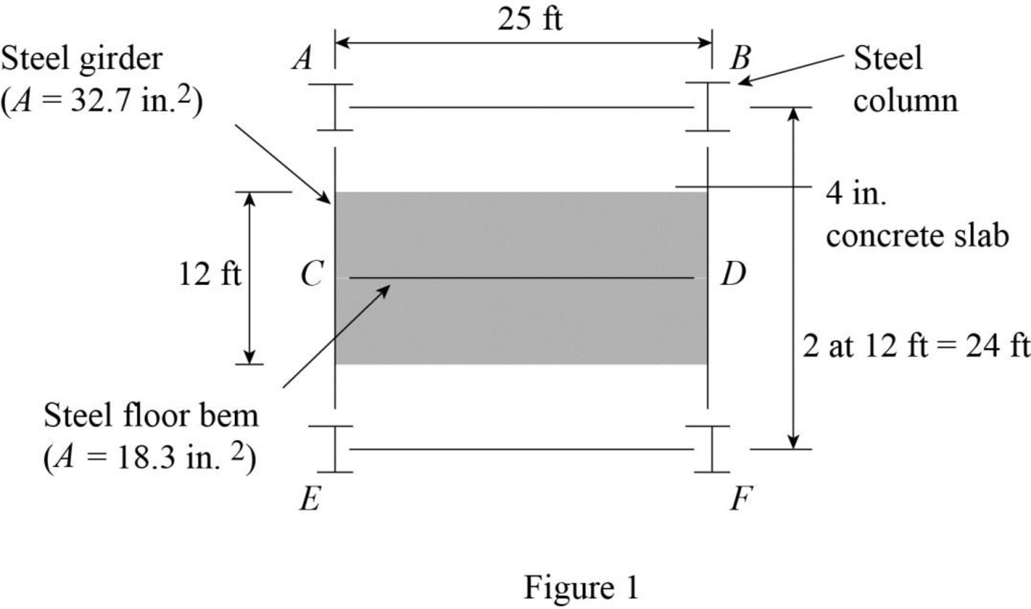
Refer Figure 1.
The tributary area of the beam CD is represented by the shaded region.
Tributary area of the beam CD:
The width of the tributary area of the beam CD is
The width of the tributary area of the beam CD is same as the length of the beam CD. Then,
The length of the tributary area of the beam CD is
The thickness of the concrete slab is
Refer Table 2.1 “Unit Weights of Construction Materials” in the text book.
The unit weight of the reinforced concrete is
The unit weight of the structural steel is
The unit weight of the brick wall is
Calculate the dead load per unit length of the beam CD as follows:
Concrete Slab:
Calculate the dead load of the concrete slab using the relation:
Substitute
Steel beam:
Calculate the dead load of the steel beam using the relation:
Substitute
Calculate the dead load of the brick wall using the relation:
Calculate the dead load of the beam CD as follows:
The dead load of
Show the dead load acting on the beam as shown in Figure 2.
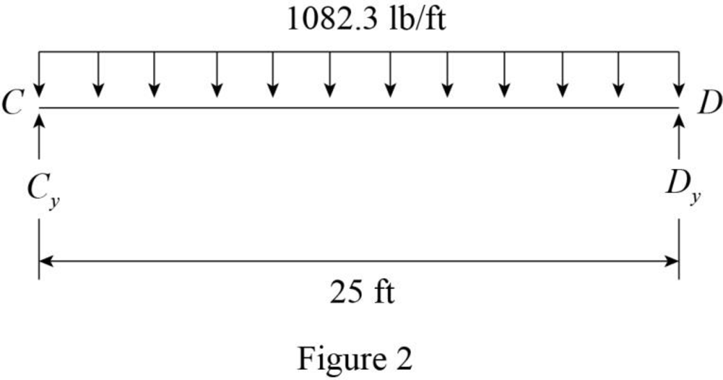
Refer Figure 2.
The reaction at C and D are denoted by
The dead load on the beam is symmetrical. Then,
Show the dead load acting on the beam as shown in Figure 3.
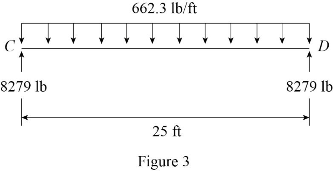
Refer Figure 3.
Thus, the dead load acting on the beam CD is
Show the floor system of the building as shown in Figure 4.
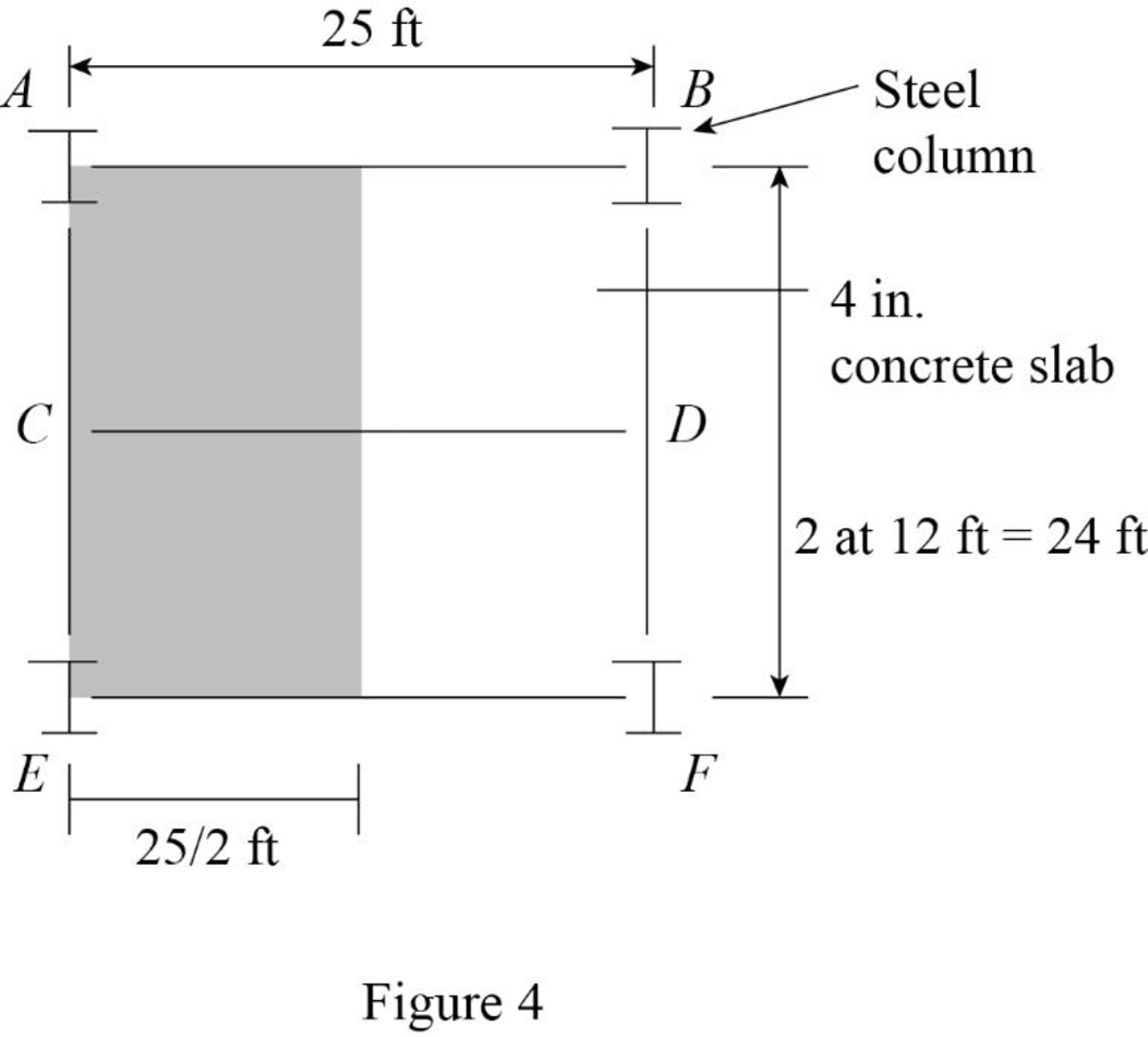
Refer Figure 4.
Tributary area of the girder AE:
The width of the tributary area of the girder AE is
The width of the tributary area of the girder AE is same as the length of the girder AE. Then,
The length of the tributary area of the girder AE is
The thickness of the reinforced concrete slab is
Calculate the dead load per unit length of the girder AE as follows:
Steel beam:
Calculate the dead load of the girder AE using the relation:
Substitute
Concentrated load at A and E.
Show the tributary area of column at A and E as shown in Figure 5.
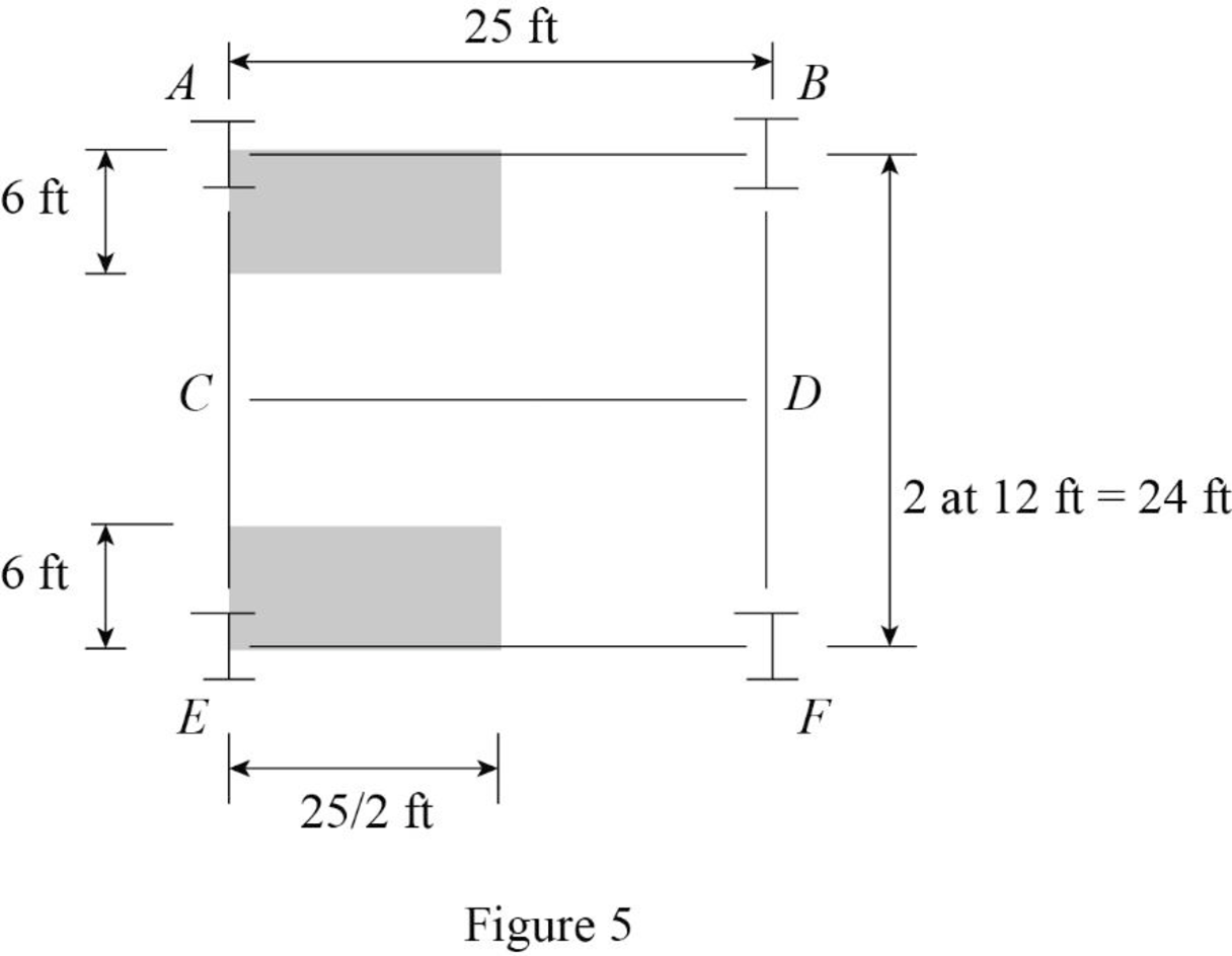
Refer Figure 5.
The tributary area of column at A and E are Equal.
The tributary area of column at A and E are
Calculate the concentrated load (P) at the column A and E the using the relation:
Substitute
Refer Figure 3.
The concentrated load at the column C is
Show the loading on the girder AE as shown in Figure 6.
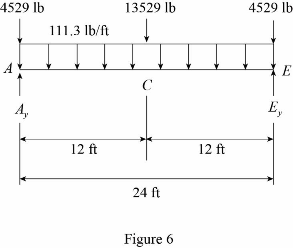
Refer Figure 6.
The reaction at A and E are denoted by
The dead load on the beam is symmetrical. Then,
Show the loading on the girder AE as shown in Figure 7.
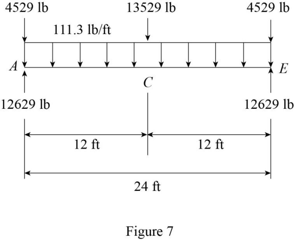
Refer Figure 7.
The dead load at C, A, and E are
The uniformly distributed load in the girder AE is
Want to see more full solutions like this?
Chapter 2 Solutions
Structural Analysis, 5th Edition


- Q1: determine the area of steel for the slab that rests on brick walls and is shown in the figure. Use the following data: f'c = 25 MPa, fy = 420 MPa, L.L. = 1.5 kN/m², D.L. = 3 kN/m² (without self-weight). Rate from (1 to 4) your ability to solve the problem 7 m 0.3 m 0.3 marrow_forwardA rigging job calls for lifting a structure that weighs 150 tons. Two cranes are available, one with a rated capacity of 85 tons and the other with a rated capacity of 120 tons. The total weight of the rigging required to make the lift is 15 tons, of which 10 tons is to be carried by the larger craneand 5 tons is to be carried by the smaller crane. If the cranes are to be loaded in proportion to their net capacities, what should be the approximate net load on the 120-ton crane?arrow_forwardI need detailed help solving this exercise from homework of Engineering Mathematics II.I do not really understand how to do, please do it step by step, not that long but clear. Thank you!P.S.: Please do not use AI, thanks!arrow_forward
- I need detailed help solving this exercise from homework of Engineering Mathematics II.I do not really understand how to do, please do it step by step, not that long but clear. Thank you!P.S.: Please do not use AI, thanks!arrow_forwarda) For the truss shown in Fig 2, determine the stiffness matrices of elements 2, 3 and 4 in the in the global co-ordinate system. Assume for each member A = 0.0015 m2 and E = 200 GPa. Indicate the degrees-of freedom in all the stiffness matrices. b) Determine the stiffness matrix of the whole truss in the global co-ordinate system. Clearly indicate the degrees-of freedom numbers in the stiffness matrix. c) Calculate all the nodal displacements and all the member forces of the truss.arrow_forwardI want an answer very quickly, pleasearrow_forward
- I want an answer very quickly, pleasearrow_forwardQ1/ Choose the correct answer for the following: 1- Cantilever retaining walls is suitable for retaining backfill about a- 8m d-4m b- 12m c- 2m e- Any height 2-The shear key is provided to a- Avoid friction behind the wall d- All of the above b- Improve appearance e- None of the above c- Increase passive resistance types of retaining wall may b- Semi-gravity retaining walls d-Counterfort retaining walls be classified as follows: 3- The common a- Gravity retaining walls walls c- Cantilever retaining e- All the mentioned 4-Related to Stability of RW, Which of the following does not represent a potential failure mode for a retaining wall? a-Bearing capacity failure of the foundation soil. b- Wall cracking due to thermal expansion. c- Excessive settlement due to weak soil layer. d- Shear failure within the foundation soil adjacent to the wall. e-Sliding along the base due to insufficient friction. 5- If the desired factor of safety against sliding is not met, which strategy is NOT a…arrow_forwardI want an answer very quickly, pleasearrow_forward
- I need a solution quickly, pleasearrow_forwardI need a solution quickly, pleasearrow_forwardFor the truss shown in Fig 2, determine the nodal displacement and member forces using the stifness method for all elements of the truss. Assume for each member A = 0.0015 m2 and E = 200 GPa please show all workingarrow_forward

 Principles of Foundation Engineering (MindTap Cou...Civil EngineeringISBN:9781305081550Author:Braja M. DasPublisher:Cengage Learning
 Principles of Foundation Engineering (MindTap Cou...Civil EngineeringISBN:9781337705028Author:Braja M. Das, Nagaratnam SivakuganPublisher:Cengage Learning
 Engineering Fundamentals: An Introduction to Engi...Civil EngineeringISBN:9781305084766Author:Saeed MoaveniPublisher:Cengage Learning
 Architectural Drafting and Design (MindTap Course...Civil EngineeringISBN:9781285165738Author:Alan Jefferis, David A. Madsen, David P. MadsenPublisher:Cengage Learning
 Fundamentals of Geotechnical Engineering (MindTap...Civil EngineeringISBN:9781305635180Author:Braja M. Das, Nagaratnam SivakuganPublisher:Cengage Learning