
Concept explainers
Find the dead loads acting on the girder AE and beam CD.
Answer to Problem 6P
The dead load acting on the beam CD is
Dead load in Girder AE:
The dead load at C, A, and E are
The uniformly distributed load in the girder AE is
Explanation of Solution
Given information:
The thickness of the reinforced concrete slab is
The area of cross-section of the steel floor beam is
The area of cross-section of the steel girder is
The length, height, and thickness of the brick wall are
Calculation:
Show the floor systemof the building as shown in Figure 1.
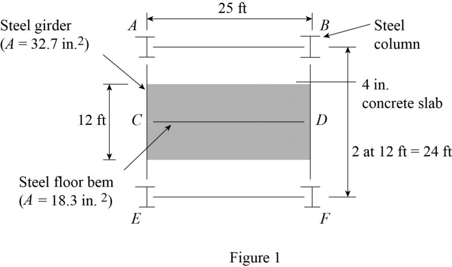
Refer Figure 1.
The tributary area of the beam CD is represented by the shaded region.
Tributary area of the beam CD:
The width of the tributary area of the beam CD is
The width of the tributary area of the beam CD is same as the length of the beam CD. Then,
The length of the tributary area of the beam CD is
The thickness of the concrete slab is
Refer Table 2.1 “Unit Weights of Construction Materials” in the text book.
The unit weight of the reinforced concrete is
The unit weight of the structural steel is
The unit weight of the brick wall is
Calculate the dead load per unit length of the beam CD as follows:
Concrete Slab:
Calculate the dead load of the concrete slab using the relation:
Substitute
Steel beam:
Calculate the dead load of the steel beam using the relation:
Substitute
Calculate the dead load of the brick wall using the relation:
Calculate the dead load of the beam CD as follows:
The dead load of
Show the dead load acting on the beam as shown in Figure 2.
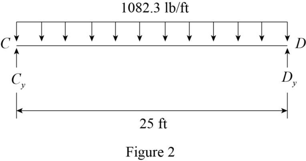
Refer Figure 2.
The reaction at C and D are denoted by
The dead load on the beam is symmetrical. Then,
Show the dead load acting on the beam as shown in Figure 3.
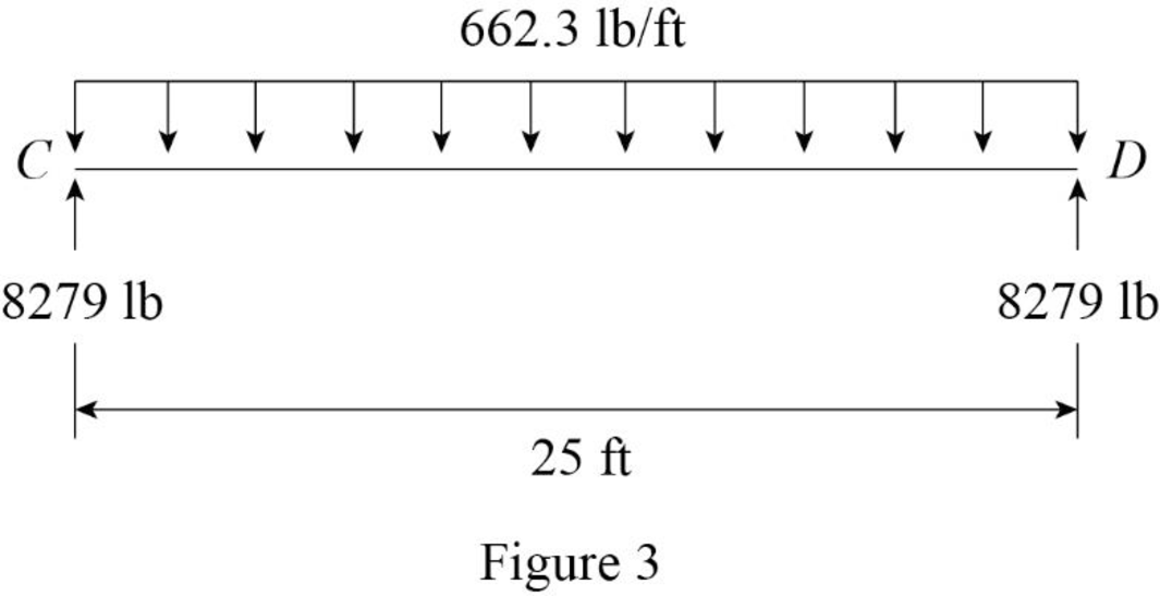
Refer Figure 3.
Thus, the dead load acting on the beam CD is
Show the floor system of the building as shown in Figure 4.
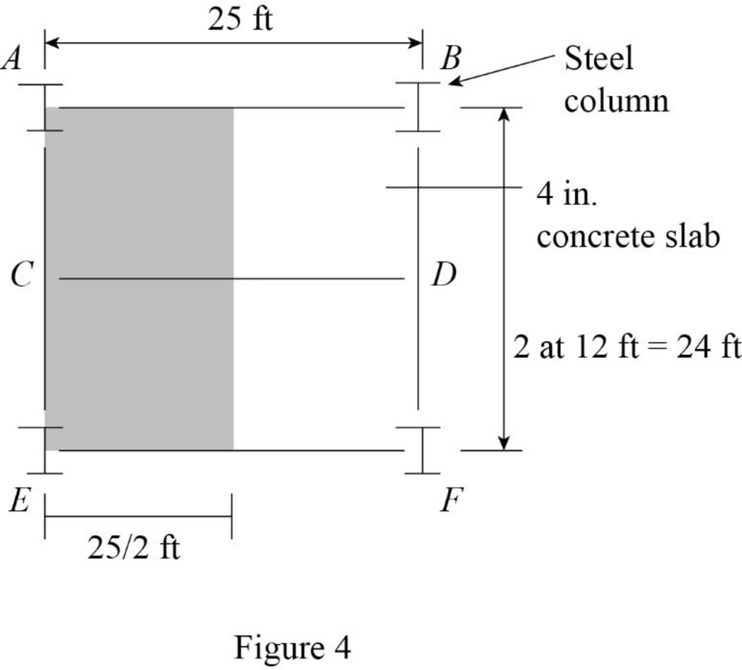
Refer Figure 4.
Tributary area of the girder AE:
The width of the tributary area of the girder AE is
The width of the tributary area of the girder AE is same as the length of the girder AE. Then,
The length of the tributary area of the girder AE is
The thickness of the reinforced concrete slab is
Calculate the dead load per unit length of the girder AE as follows:
Steel beam:
Calculate the dead load of the girder AE using the relation:
Substitute
Concentrated load at A and E.
Show the tributary area of column at A and E as shown in Figure 5.
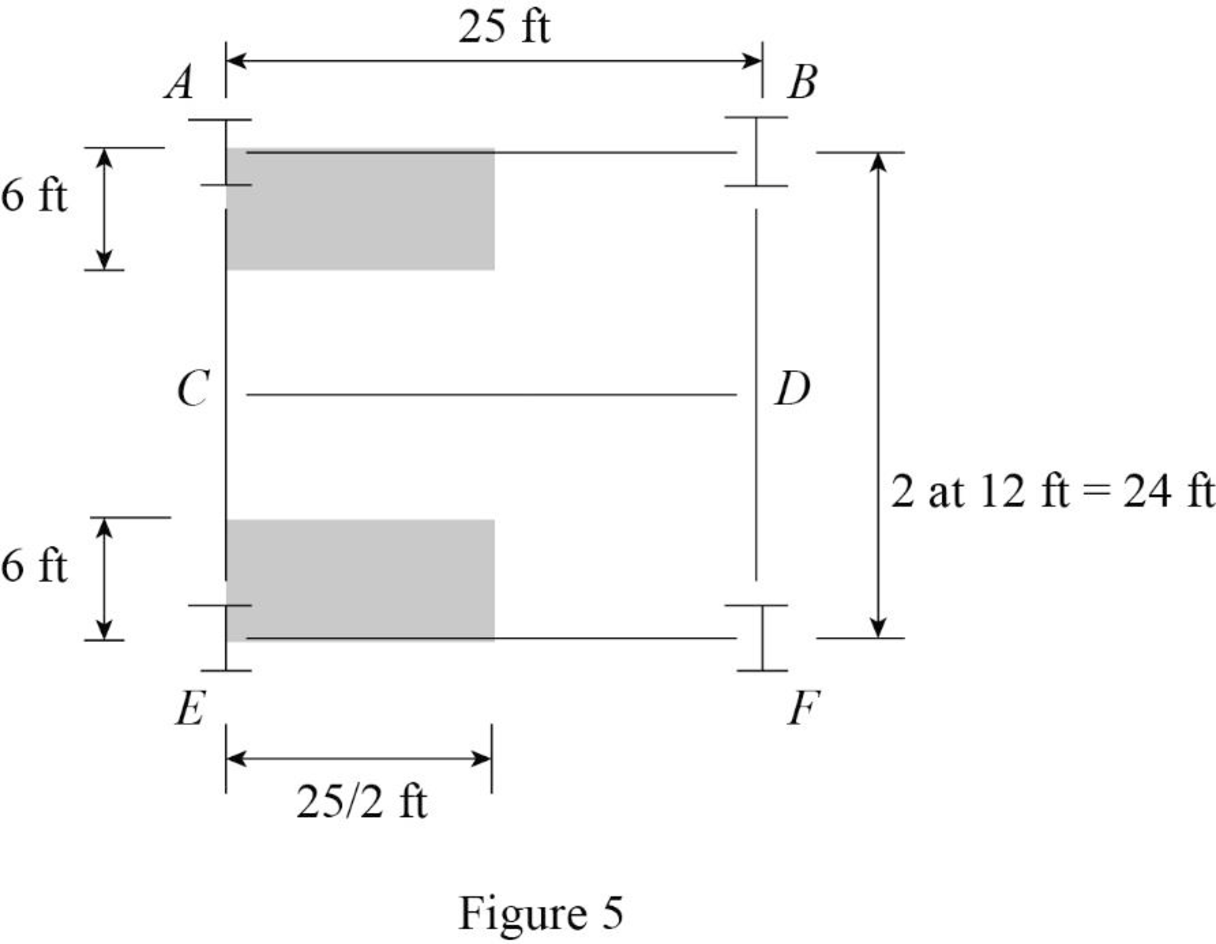
Refer Figure 5.
The tributary area of column at A and E are Equal.
The tributary area of column at A and E are
Calculate the concentrated load (P) at the column A and E the using the relation:
Substitute
Refer Figure 3.
The concentrated load at the column C is
Show the loading on the girder AE as shown in Figure 6.
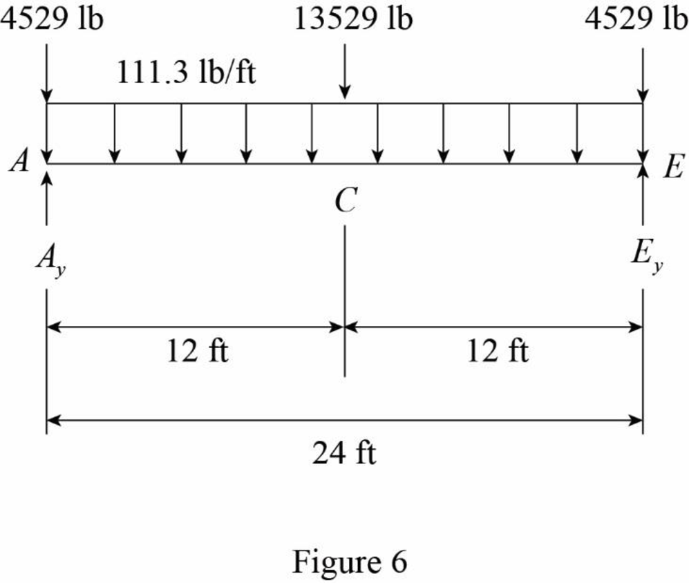
Refer Figure 6.
The reaction at A and E are denoted by
The dead load on the beam is symmetrical. Then,
Show the loading on the girder AE as shown in Figure 7.
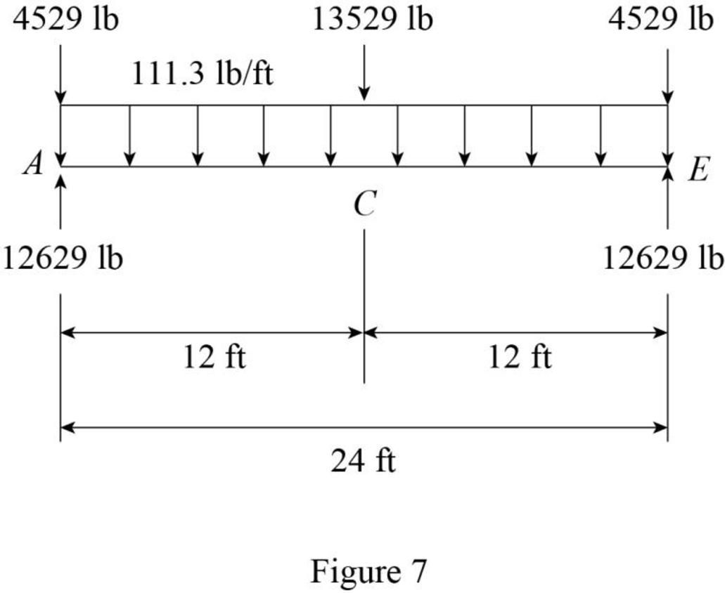
Refer Figure 7.
The dead load at C, A, and E are
The uniformly distributed load in the girder AE is
Want to see more full solutions like this?
Chapter 2 Solutions
EBK STRUCTURAL ANALYSIS


- Please answer the question in the picture, show all of you work in pictures and handwritten.arrow_forward2nd monthly 4th. Year- exam Hydraulic Structures 9/12/201 QL Check the floor thickness the cutoff depths and the horizontal floor length for the given regulator using Lane's method. u/s. W.L. u/s. B.L 24.25 = 20.50 m x Discharge Q = 60 m³/s Waterway S = Duis 3.5 m 10 m Distance from u/s pile line Cd = 0.9 C = 6.5 Concrete floor thickness. D/S.W.L.. D/S. B.L. 24.00 th = 19.65 m u/s. canal bed width = 15 m Horizontal floor length L₁ = 51 m D 6m to the gate silt factor f under the gate 9.0m = 0.7 beginning' · of floor. at at end 2.4 ton / m³ 3m 1 = m I m Fronc Q.2. What is the function of 0 u/s cutoff 4 Fish ladder ③ D/S cutoff Lock The flow net Intermediate oile Al-Mansour University College U/S guid bankarrow_forwardFor the portal frame determine the reactions at a using the approximate method if all supports are fixed.arrow_forward
- Please answer the question in the picture.arrow_forwardPlease answer the question in the picture. Thank you so much for your help!arrow_forwardI dont understand how to do the hand calculations help pls A multi-cell box beam, 1800 mm long, is subject to a vertical shear load of 6 kN applied in a vertical plane. Points 1-8 mark the boom elements on the beam. Calculate the shear flow in each web and locate the shear centre using hand calculations. The results, including mesh convergence, shear flow, stress distribution, deformation, and shear centre location, will then be compared with findings from Abaqus FEA. The material properties are: Young's modulus (E) is 72 GPa, and Poisson's ratio (ν) is 0.3.arrow_forward
- find the following (show all work) Seepage velocity vs (m/sec) Discharge velocity v (m/sec) Hydraulic Conductivity k (m/sec) given : length of specimen 0.25 m , Diameter of specimen 0.10 m , Head difference 0.50 m , water collected in 2 minutes, 50 ml, the void ratio of soil 0.46arrow_forwarddraw sketches to comment the different components of the total head (Bernoulli's equation) Define head loss Explain the differences between a seepage and a discharge velocities in soil. Are they related if so in what way.arrow_forwardQ1: Determine the duration of project for the activities shown below, and find the critical path by using (A-0- Diagram) ABC DEFOHIJKMN R 4 5 6 8 3 7 8 11 3 8 3 7 8 11 3 8 489 4 Activity Duration (Weeks) Followed C,D D,F JJHOK MIK NMR- by E 1arrow_forward
- I dont understand how to do the hand calculations help pls A multi-cell box beam, 1800 mm long, is subject to a vertical shear load of 6 kN applied in a vertical plane. Points 1-8 mark the boom elements on the beam. Calculate the shear flow in each web and locate the shear centre using hand calculations. The results, including mesh convergence, shear flow, stress distribution, deformation, and shear centre location, will then be compared with findings from Abaqus FEA. The material properties are: Young's modulus (E) is 72 GPa, and Poisson's ratio (ν) is 0.3.arrow_forward2. Vertical highway curve: Given PVI at 65 + 00, L = 800 ft, g1 = +4%, g2 = -3%, and PVI elevation = 264.2 ft, compute the elevations of the curve high point and for all of the full stations until reaching the end of the curve as well as for the beginning and end of the curve.arrow_forward1. Horizontal highway curve: Given Pl at 65 + 78.20, A = 22°00', and D = 6°00', compute the deflections to the nearest second for the full stations (means stations 65+00, 66+00, etc.) as well as for the beginning and end of the curve.arrow_forward

 Principles of Foundation Engineering (MindTap Cou...Civil EngineeringISBN:9781305081550Author:Braja M. DasPublisher:Cengage Learning
 Principles of Foundation Engineering (MindTap Cou...Civil EngineeringISBN:9781337705028Author:Braja M. Das, Nagaratnam SivakuganPublisher:Cengage Learning
 Engineering Fundamentals: An Introduction to Engi...Civil EngineeringISBN:9781305084766Author:Saeed MoaveniPublisher:Cengage Learning
 Architectural Drafting and Design (MindTap Course...Civil EngineeringISBN:9781285165738Author:Alan Jefferis, David A. Madsen, David P. MadsenPublisher:Cengage Learning
 Fundamentals of Geotechnical Engineering (MindTap...Civil EngineeringISBN:9781305635180Author:Braja M. Das, Nagaratnam SivakuganPublisher:Cengage Learning