
Principles Of Electric Circuits
10th Edition
ISBN: 9780134879482
Author: Floyd, Thomas L.
Publisher: Pearson,
expand_more
expand_more
format_list_bulleted
Concept explainers
Videos
Textbook Question
Chapter 2, Problem 45PQ
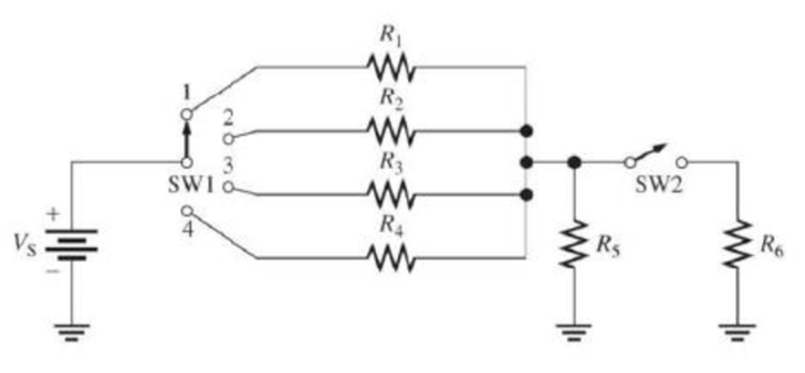
In Figure 2–69, show the proper placement of ammeters to measure the current through each resistor and the current out of the battery.
Figure 2–69
Expert Solution & Answer
Want to see the full answer?
Check out a sample textbook solution
Students have asked these similar questions
Cable A
Cable A is a coaxial cable of constant cross section. The metal
regions are shaded in grey and are made of copper. The solid central
wire has radius a = 5mm, the outer tube inner radius b = 20mm and
thickness t = 5mm. The dielectric spacer is Teflon, of relative
permittivity &r = 2.1 and breakdown strength 350kV/cm. A potential
difference of 1kV is applied across the conductors, with centre
conductor positive and outer conductor earthed.
Before undertaking any COMSOL simulations we'll first perform some theoretical analysis
of Cable A based on the EN2076 lectures, to make sense of the simulations. Calculate the
radial electric field of cable A at radial positions r b. Also calculate the
maximum operating voltage of cable A, assuming a safety margin of ×2, and indicate where
on the cable's cross section dielectric breakdown is most likely to occur.
: For the gravity concrete dam shown in the figure, the following data are available:
The factor of safety against sliding (F.S sliding)=1.2
Unit weight of concrete (Yconc)=24 KN/m³
- Neglect( Wave pressure, silt pressure, ice force and earth quake force)
μ=0.65, (Ywater) = 9.81 KN/m³
Find factor of safety against overturning (F.S overturning)
6m3
80m
Sm
I need help checking if its correct
-E1 + VR1 + VR4 – E2 + VR3 = 0 -------> Loop 1 (a)
R1(I1) + R4(I1 – I2) + R3(I1) = E1 + E2 ------> Loop 1 (b)
R1(I1) + R4(I1) - R4(I2) + R3(I1) = E1 + E2 ------> Loop 1 (c)
(R1 + R3 + R4) (I1) - R4(I2) = E1 + E2 ------> Loop 1 (d)
Now that we have loop 1 equation will procced on finding the equation of I2 current loop. However, a reminder that because we are going in a clockwise direction, it goes against the direction of the current. As such we will get an equation for the matrix that will be:
E2 – VR4 – VR2 + E3 = 0 ------> Loop 2 (a)
-R4(I2 – I1) -R2(I2) = -E2 – E3 ------> Loop 2 (b)
-R4(I2) + R4(I1) - R2(I2) = -E2 – E3 -----> Loop 2 (c)
R4(I1) – (R4 + R2)(I2) = -E2 – E3 -----> Loop 2 (d)
These two equations will be implemented to the matrix formula I = inv(A) * b
R11 R12
(R1 + R3 + R4)
-R4
-R4
R4 + R2
Chapter 2 Solutions
Principles Of Electric Circuits
Ch. 2 - How many coulombs do 93.8 1016 electrons...Ch. 2 - How much energy is required to move 50 C from one...Ch. 2 - If there are 2.0 A of current through the filament...Ch. 2 - A certain resistor has a yellow first band, a...Ch. 2 - A certain resistor has a yellow first band, a...Ch. 2 - What is the resistance indicated by 1K25?Ch. 2 - What is the cross-sectional area of a 0.0015 in....Ch. 2 - Use Table 2-3 to determine the resistance of 100...Ch. 2 - Related Problem In Figure 257 the switch is moved...Ch. 2 - The number of protons in the nucleus is the atomic...
Ch. 2 - The outermost shell of an atom contains the...Ch. 2 - Silicon and germanium are classed as insulators.Ch. 2 - The unit of charge is ampere.Ch. 2 - Like charges repel.Ch. 2 - Coulombs law shows the relationship of the energy...Ch. 2 - A battery stores charge.Ch. 2 - An ideal voltage source can provide a constant...Ch. 2 - A volt can be defined in terms of energy per...Ch. 2 - A fuel cell combines a fuel with an oxidizer to...Ch. 2 - The unit of current is coulomb.Ch. 2 - In a 5-band precision resistor, the fourth band is...Ch. 2 - A resistor with a single black band represents...Ch. 2 - A resistor labeled 0R1 is 1 ohm.Ch. 2 - A rheostat performs the same function as a...Ch. 2 - A strain gauge changes resistance in response to...Ch. 2 - Prob. 17TFQCh. 2 - A circular mil is a unit of area.Ch. 2 - The three basic measurements that can be done by a...Ch. 2 - If a GFCI breaker detects a difference in the hot...Ch. 2 - A neutral atom with an atomic number of three has...Ch. 2 - Electron orbits are called 1. shells 2. nuclei 3....Ch. 2 - Materials in which there is no current when...Ch. 2 - When placed close together, a positively charged...Ch. 2 - The charge on a single electron is 1. 6.25 1018 C...Ch. 2 - Potential difference is another term for 1. energy...Ch. 2 - The unit of energy is the 1. watt 2. coulomb 3....Ch. 2 - Which one of the following is not a type of energy...Ch. 2 - Which one of the following is not a possible...Ch. 2 - Electrical current is defined as 1. the reciprocal...Ch. 2 - There is no current in a circuit when 1. a switch...Ch. 2 - The primary purpose of a resistor is to 1....Ch. 2 - Wire resistance depends on the 1. type of material...Ch. 2 - Potentiometers and rheostats are types of 1....Ch. 2 - The current in a given circuit is not to exceed 22...Ch. 2 - The neutral line in a ac utility should 1. have...Ch. 2 - What is the charge in coulombs of the nucleus of a...Ch. 2 - What is the charge in coulombs of the nucleus of a...Ch. 2 - How many coulombs of charge do 50 1031 electrons...Ch. 2 - How many electrons does it take to make 80 C...Ch. 2 - Determine the voltage in each of the following...Ch. 2 - Five hundred joules of energy are used to move 100...Ch. 2 - What is the voltage of a battery that uses 24 J of...Ch. 2 - How much energy does a 12 V battery use to move...Ch. 2 - If a resistor with a current of 20 mA through it...Ch. 2 - List four common sources of voltage.Ch. 2 - Upon what principle is electrical generators...Ch. 2 - How does and electronic power supply differ from...Ch. 2 - A certain current source provides 100 mA to a 1 k...Ch. 2 - Determine the current in each of the following...Ch. 2 - Six-tenths coulomb passes a point in 3 s. What is...Ch. 2 - How long does it take 10 C to flow past a point if...Ch. 2 - How many coulombs pass a point in 0.1 s when the...Ch. 2 - 5.74 1017 electrons flow through a wire in 250...Ch. 2 - Find the conductance for each of the following...Ch. 2 - Find the resistance corresponding to the following...Ch. 2 - Determine the resistance values and tolerance for...Ch. 2 - Find the minimum and the maximum resistance within...Ch. 2 - Determine the color bands for each of the...Ch. 2 - Determine the resistance and tolerance of each of...Ch. 2 - Determine the resistance and percent tolerance for...Ch. 2 - From the selection of resistors in Figure 267,...Ch. 2 - Determine the color bands for each of the...Ch. 2 - Determine the resistance and tolerance of each of...Ch. 2 - Determine the color bands for each of the...Ch. 2 - The adjustable contact of a linear potentiometer...Ch. 2 - What resistance is indicated by 4K7?Ch. 2 - Determine the resistance and tolerance of each...Ch. 2 - Trace the current path in Figure 268(a) with the...Ch. 2 - With the switch in either position, redraw the...Ch. 2 - There is only one circuit in Figure 268 in which...Ch. 2 - In Figure 268, determine which (if any) circuits...Ch. 2 - In Figure 268, determine which (if any) circuits...Ch. 2 - Through which resistor in Figure 269 is there...Ch. 2 - Devise a switch arrangement whereby two voltage...Ch. 2 - Show how a single switch can be used to connect a...Ch. 2 - Show the placement of an ammeter and a voltmeter...Ch. 2 - Prob. 42PQCh. 2 - In Figure 271, how much voltage does each meter...Ch. 2 - In Figure 271, indicate how to connect an ammeter...Ch. 2 - In Figure 269, show the proper placement of...Ch. 2 - Show the proper placement of voltmeters to measure...Ch. 2 - What is the voltage reading of the meter in Figure...Ch. 2 - How much resistance is the ohmmeter in Figure...Ch. 2 - Determine the resistance indicated by each of the...Ch. 2 - What is the maximum resolution of a 4-digit DMM?Ch. 2 - Indicate how you would connect the multimeter in...
Knowledge Booster


Learn more about
Need a deep-dive on the concept behind this application? Look no further. Learn more about this topic, electrical-engineering and related others by exploring similar questions and additional content below.Similar questions
- 10.2 For each of the following groups of sources, determineif the three sources constitute a balanced source, and if it is,determine if it has a positive or negative phase sequence.(a) va(t) = 169.7cos(377t +15◦) Vvb(t) = 169.7cos(377t −105◦) Vvc(t) = 169.7sin(377t −135◦) V(b) va(t) = 311cos(wt −12◦) Vvb(t) = 311cos(wt +108◦) Vvc(t) = 311cos(wt +228◦) V(c) V1 = 140 −140◦ VV2 = 114 −20◦ VV3 = 124 100◦ Varrow_forwardApply single-phase equivalency to determine the linecurrents in the Y-D network shown in Fig. P10.13. The loadimpedances are Zab = Zbc = Zca = (25+ j5) Warrow_forward10.8 In the network of Fig. P10.8, Za = Zb = Zc = (25+ j5) W.Determine the line currents.arrow_forward
- Using D flip-flops, design a synchronous counter. The counter counts in the sequence 1,3,5,7, 1,7,5,3,1,3,5,7,.... when its enable input x is equal to 1; otherwise, the counter count 0. Present state Next state x=0 Next state x=1 Output SO 52 S1 1 S1 54 53 3 52 53 S2 56 51 0 $5 5 54 S4 53 0 55 58 57 7 56 56 55 0 57 S10 59 1 58 58 S7 0 59 S12 S11 7 $10 $10 59 0 $11 $14 $13 5 $12 S12 $11 0 513 $15 SO 3 S14 $14 S13 0 $15 515 SO 0 Explain how to get the table step by step with drawing the state diagram and finding the Karnaugh map.arrow_forwardFor the oscillator resonance circuit shown in Fig. (5), derive the oscillation frequency Feedback and open-loop gains. L₁ 5 mH (a) ell +10 V R₁ ww R3 S C2 HH 1 με 1000 pF 100 pF R₂ 1 με RA H (b) +9 V R4 CA 470 pF C₁ R3 HH 1 με R₁ ww L₁ 000 1.5 mH R₂ ww Hi 1 μF L2 m 10 mHarrow_forwardExpert handwritten solution onlyarrow_forward
- B. For the oscillator circuit shown in frequency, feedback and open-loop gains. +10 V name the circuit, derive and find the oscillation P.Av +9 V -000 4₁ 5 mH w R₁ C₂ HH 1 με w 100 pF R₂ T R CA www. 470 pF w ww www 1000 pF HH 1μF C₁ HH 1μF Ra ww HI 4₁ 000 1.5 mH H 4 AF 000 10 mHarrow_forwardI want to check if the current that I have from using the mesh analysis is correct? I1 = 0.214mA I2 = -0.429mAarrow_forwardI want to find the current by using mesh analysis pleasearrow_forward
- I want to find the current by using mesh analysis pleasearrow_forwardR₁ W +10 V R3 +9 V C₂ R₁ CA C₁ 470 pF HH 1000 pF HH 1 με C4 1 μF 1 uF C₁ R₂ R4 100 pF Find Open-loop Jain L₁ 5 mH (a) Av=S,B={" H R₁₂ ✓ ww (b) R₁ L₁ 000 1.5 mH R₂ H 1 uF 12 10 mHarrow_forwardA) Calculate the efficiency of the test transformer at the resistive loads (X-25%, 50%, 75%, 100%, 125% full load). B) From part (A) draw the plot (efficiency Vs power output) of the transformer. C) Discuss the plot of part (B).arrow_forward
arrow_back_ios
SEE MORE QUESTIONS
arrow_forward_ios
Recommended textbooks for you
 Electricity for Refrigeration, Heating, and Air C...Mechanical EngineeringISBN:9781337399128Author:Russell E. SmithPublisher:Cengage Learning
 Delmar's Standard Textbook Of ElectricityElectrical EngineeringISBN:9781337900348Author:Stephen L. HermanPublisher:Cengage Learning
Electricity for Refrigeration, Heating, and Air C...
Mechanical Engineering
ISBN:9781337399128
Author:Russell E. Smith
Publisher:Cengage Learning
Delmar's Standard Textbook Of Electricity
Electrical Engineering
ISBN:9781337900348
Author:Stephen L. Herman
Publisher:Cengage Learning
Conductivity and Semiconductors; Author: Professor Dave Explains;https://www.youtube.com/watch?v=5zz6LlDVRl0;License: Standard Youtube License