
Fundamentals of Applied Electromagnetics (7th Edition)
7th Edition
ISBN: 9780133356984
Author: ULABY
Publisher: PEARSON
expand_more
expand_more
format_list_bulleted
Concept explainers
Videos
Textbook Question
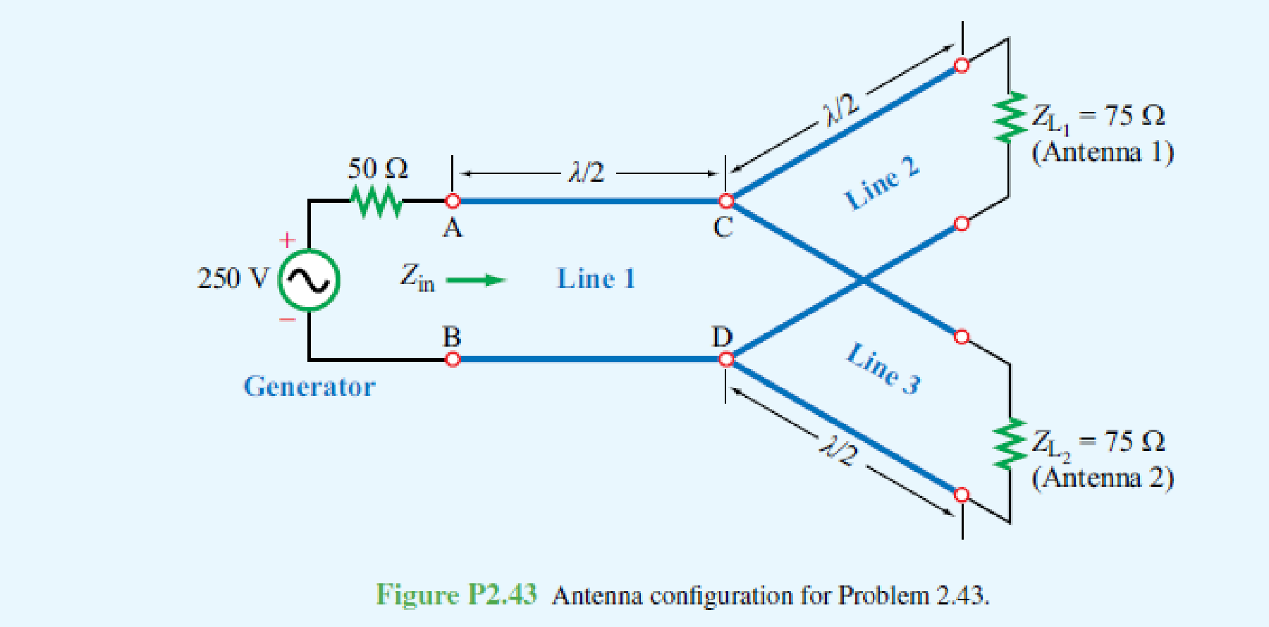
Chapter 2, Problem 43P
If the two-antenna configuration shown in Fig. P2.43 is connected to a generator with
Expert Solution & Answer
Want to see the full answer?
Check out a sample textbook solution
Students have asked these similar questions
General Directions: Read the questions carefully and answer (3*10=30marks)
1. Design a summing amplifier by choosing appropriate values of resistors an so that
the output is 5 times the sum of the input voltages. (you are free to use any number
of inputs, the type of op-amp, any value of resistors)
2. Derive the equation for the closed loop gain of the inverting and non-inverting
Amplifier using appropriate circuit diagrams.
3. Determine the values read by the measuring devices using appropriate formulae
www
Voc
+8V
R₁
33 k
Rc
2.2 k
ww
WWW
Poc 200
R₁₂
RE
10 kn
1.0 kn
十
: + B
日
العنوان
I need a detailed drawing with explanation
ややハメPV+96252
4
Project Homework:
Create a simulation for a tank when the flowrate inside and outside the tank must
range between 0 and 10 lit/s:
1) The level should be controlled within a range between more than zero to 1000
lit.
2) An alarm must be launched when the level is out of range (less than 100 and
more than 900 lit).
3) When the capacity reaches to the maximum the motor turns OFF.
area=A
Qout
-20
solve in lab view
X9.01
*175*1
Project Homework:
Create a simulation for a tank when the flowrate inside and outside the tank must
range between 0 and 10 lit/s:
1) The level should be controlled within a range between more than zero to 1000
lit.
2) An alarm must be launched when the level is out of range (less than 100 and
more than 900 lit).
3) When the capacity reaches to the maximum the motor turns OFF.
Qin
h
C
Qout
area=A
solve in lab view
Chapter 2 Solutions
Fundamentals of Applied Electromagnetics (7th Edition)
Ch. 2.2 - What is a transmission line? When should...Ch. 2.2 - Prob. 2CQCh. 2.2 - What constitutes a TEM transmission line?Ch. 2.2 - Prob. 4CQCh. 2.2 - Prob. 1ECh. 2.2 - Calculate the transmission line parameters at 1...Ch. 2.4 - Verify that Eq. (2.26a) indeed provides a solution...Ch. 2.4 - A two-wire air line has the following line...Ch. 2.6 - The attenuation constant represents ohmic losses....Ch. 2.6 - How is the wavelength of the wave traveling on...
Ch. 2.6 - Prob. 7CQCh. 2.6 - What is a standing-wave pattern? Why is its period...Ch. 2.6 - Prob. 9CQCh. 2.6 - For a lossless transmission line, = 20.7 cm at 1...Ch. 2.6 - A lossless transmission line uses a dielectric...Ch. 2.6 - Prob. 7ECh. 2.6 - Prob. 8ECh. 2.6 - Prob. 10ECh. 2.6 - A 140 lossless line is terminated in a load...Ch. 2.8 - What is the difference between the characteristic...Ch. 2.8 - What is a quarter-wave transformer? How can it be...Ch. 2.8 - Prob. 12CQCh. 2.8 - Prob. 13CQCh. 2.8 - if the input impedance of a lossless line is...Ch. 2.8 - Prob. 12ECh. 2.8 - A 300 feedline is to be connected to a 3 m long,...Ch. 2.9 - According to Eq. (2.102b), the instantaneous value...Ch. 2.9 - Prob. 16CQCh. 2.9 - What fraction of the incident power is delivered...Ch. 2.9 - Prob. 18CQCh. 2.9 - For a 50 lossless transmission line terminated in...Ch. 2.9 - For the line of Exercise 2-14, what is the...Ch. 2.10 - The outer perimeter of the Smith chart represents...Ch. 2.10 - What is an SWR circle? What quantities are...Ch. 2.10 - What line length corresponds to one complete...Ch. 2.10 - Which points on the SWR circle correspond to...Ch. 2.10 - Prob. 23CQCh. 2.10 - Use the Smith chart to find the values of ...Ch. 2.11 - Prob. 24CQCh. 2.11 - Prob. 25CQCh. 2.12 - What is transient analysis used for?Ch. 2.12 - Prob. 28CQCh. 2.12 - What is the difference between the bounce diagram...Ch. 2 - A transmission line of length l connects a load to...Ch. 2 - Show that the transmission-line model shown in...Ch. 2 - A 1 GHz parallel-plate transmission line consists...Ch. 2 - For the parallel-plate transmission line of...Ch. 2 - In addition to not dissipating power, a lossless...Ch. 2 - For a distortionless line [see Problem 2.13] with...Ch. 2 - Prob. 15PCh. 2 - A transmission line operating at 125 MHz has Z0 =...Ch. 2 - Prob. 17PCh. 2 - Polyethylene with r=2.25 is used as the insulating...Ch. 2 - Prob. 20PCh. 2 - Prob. 21PCh. 2 - Prob. 22PCh. 2 - Prob. 23PCh. 2 - A 50 lossless line terminated in a purely...Ch. 2 - Prob. 26PCh. 2 - Prob. 27PCh. 2 - Prob. 29PCh. 2 - Prob. 30PCh. 2 - Two half-wave dipole antennas, each with an...Ch. 2 - Prob. 34PCh. 2 - For the lossless transmission line circuit shown...Ch. 2 - A lossless transmission line is terminated in a...Ch. 2 - The input impedance of a 31 cm long lossless...Ch. 2 - FM broadcast station uses a 300 transmission line...Ch. 2 - A generator with Vg=300 V and Zg = 50 is...Ch. 2 - If the two-antenna configuration shown in Fig....Ch. 2 - For the circuit shown in Fig. P2.44, calculate the...Ch. 2 - The circuit shown in Fig. P2.45 consists of a 100 ...Ch. 2 - An antenna with a load impedance ZL=(75+j25) is...Ch. 2 - Prob. 47PCh. 2 - Use the Smith chart to determine the input...Ch. 2 - Prob. 52PCh. 2 - A lossless 50 transmission line is terminated in...Ch. 2 - A lossless 50 transmission line is terminated in...Ch. 2 - Use the Smith chart to find yL if zL = 1.5 j0.7.Ch. 2 - Prob. 59PCh. 2 - Prob. 62PCh. 2 - Determine Zin of the feed line shown in Fig....Ch. 2 - Prob. 73PCh. 2 - A 25 antenna is connected to a 75 lossless...Ch. 2 - Prob. 75PCh. 2 - Prob. 76PCh. 2 - Prob. 77PCh. 2 - In response to a step voltage, the voltage...Ch. 2 - Suppose the voltage waveform shown in Fig. P2.77...Ch. 2 - For the circuit of Problem 2.80, generate a bounce...Ch. 2 - In response to a step voltage, the voltage...
Knowledge Booster


Learn more about
Need a deep-dive on the concept behind this application? Look no further. Learn more about this topic, electrical-engineering and related others by exploring similar questions and additional content below.Similar questions
- QUESTION [3] A no-load and short-circuit test should be conducted on a 220V/110V, 280VA transformer. a. Draw the circuit diagram for the no-load test and include all measurements that should be made. Also write down the maximum voltage that you should apply to the primary winding and estimate the current drawn from the supply. (5) b. Draw a circuit diagram for the short-circuit test and include all measurements that should be made. Also write down the maximum current that should be allowed to flow in the primary winding and estimated the primary voltage that will cause this value of the current to flow. (5)arrow_forwardOnly expert should solve it pleasearrow_forwardNeed handwritten solution pleasearrow_forward
- Design a lowpass FIR filter using frequency sampling technique having cut-off frequency of T/2 rad/sample. The filter should have linear phase and length of 17.arrow_forwardA dc compound motor having a rating of 10 kW, 1150 r/min, 230 V, 50 A, has the following losses at full-load: bearing friction loss 40 W brush friction loss == 50 W windage loss = 200 W (1) total mechanical losses = 290 W (2) iron losses = 420 W (3) copper loss in the shunt field = 120 W copper losses at full-load: (4) a. in the armature b. in the series field c. in the commutating winding total copper loss in the 500 W 25 W 70 W armature circuit at full-load = 595 Warrow_forward4 What determines the power rating of a ma- chine? -5 If we cover up the vents in a motor, its out- put power must be reduced. Explain. -6 If a motor operates in a cold environment, may we load it above its rated power? Why?arrow_forward
- An electric motor driving a skip hoist with- draws 1.5 metric tons of minerals from a trench 20 m deep every 30 seconds. If the hoist has an overall efficiency of 94 percent, calculate the power output of the motor in horsepower and in kilowatts.arrow_forwardThe efficiency of a motor is always low when it operates at 10 percent of its nominal power rating. Explain.arrow_forwardA dc motor connected to a 240 V line pro- duces a mechanical output of 160 hp. Knowing that the losses are 12 kW, calculate the input power and the line current.arrow_forward
- A 115 V dc generator delivers 120 A to a load. If the generator has an efficiency of 81 percent, calculate the mechanical power needed to drive it [hp].arrow_forwardA machine having class B insulation attains a temperature of 208°C (by resistance) in a torrid ambient temperature of 180°C. a. What is the temperature rise? b. Is the machine running too hot and, if so, by how much?arrow_forward1 Name the losses in a dc motor. 2 What causes iron losses and how can they be reduced? -3 Explain why the temperature of a machine increases as the load increases.arrow_forward
arrow_back_ios
SEE MORE QUESTIONS
arrow_forward_ios
Recommended textbooks for you
 Introductory Circuit Analysis (13th Edition)Electrical EngineeringISBN:9780133923605Author:Robert L. BoylestadPublisher:PEARSON
 Delmar's Standard Textbook Of ElectricityElectrical EngineeringISBN:9781337900348Author:Stephen L. HermanPublisher:Cengage Learning
 Programmable Logic ControllersElectrical EngineeringISBN:9780073373843Author:Frank D. PetruzellaPublisher:McGraw-Hill Education
 Fundamentals of Electric CircuitsElectrical EngineeringISBN:9780078028229Author:Charles K Alexander, Matthew SadikuPublisher:McGraw-Hill Education
 Electric Circuits. (11th Edition)Electrical EngineeringISBN:9780134746968Author:James W. Nilsson, Susan RiedelPublisher:PEARSON
 Engineering ElectromagneticsElectrical EngineeringISBN:9780078028151Author:Hayt, William H. (william Hart), Jr, BUCK, John A.Publisher:Mcgraw-hill Education,
Introductory Circuit Analysis (13th Edition)
Electrical Engineering
ISBN:9780133923605
Author:Robert L. Boylestad
Publisher:PEARSON
Delmar's Standard Textbook Of Electricity
Electrical Engineering
ISBN:9781337900348
Author:Stephen L. Herman
Publisher:Cengage Learning
Programmable Logic Controllers
Electrical Engineering
ISBN:9780073373843
Author:Frank D. Petruzella
Publisher:McGraw-Hill Education
Fundamentals of Electric Circuits
Electrical Engineering
ISBN:9780078028229
Author:Charles K Alexander, Matthew Sadiku
Publisher:McGraw-Hill Education
Electric Circuits. (11th Edition)
Electrical Engineering
ISBN:9780134746968
Author:James W. Nilsson, Susan Riedel
Publisher:PEARSON
Engineering Electromagnetics
Electrical Engineering
ISBN:9780078028151
Author:Hayt, William H. (william Hart), Jr, BUCK, John A.
Publisher:Mcgraw-hill Education,
How does an Antenna work? | ICT #4; Author: Lesics;https://www.youtube.com/watch?v=ZaXm6wau-jc;License: Standard Youtube License