Concept explainers
Calculate the hydrodynamic load applied at floor level on the wall IJKL due to outflow for load cases 2 and 3.
Calculate the hydrostatic loading on the adjacent outside walls due to water retained by the floor and the debris impact load applied to the free standing column CD.
Answer to Problem 22P
The hydrodynamic load applied at floor level on the wall IJKL due to outflow for load case 2 is
The hydrodynamic load applied at floor level on the wall IJKL at J due to outflow for load case 3 is
The hydrodynamic load applied at floor level on the wall IJKL at K due to outflow for load case 3 is
The hydrostatic loading on the adjacent outside walls due to water retained by the floor is
Explanation of Solution
Given information:
The width of the building (B) is 35 ft.
The maximum inundation height
The flow velocity
Assume
Calculation:
For load case 2:
Calculate the height of the water applicable to the structure
Calculate the velocity of flow applicable to the structure
Sketch the load applied at floor level on the wall IJKL due to outflow for load case 2 as shown in Figure 1.
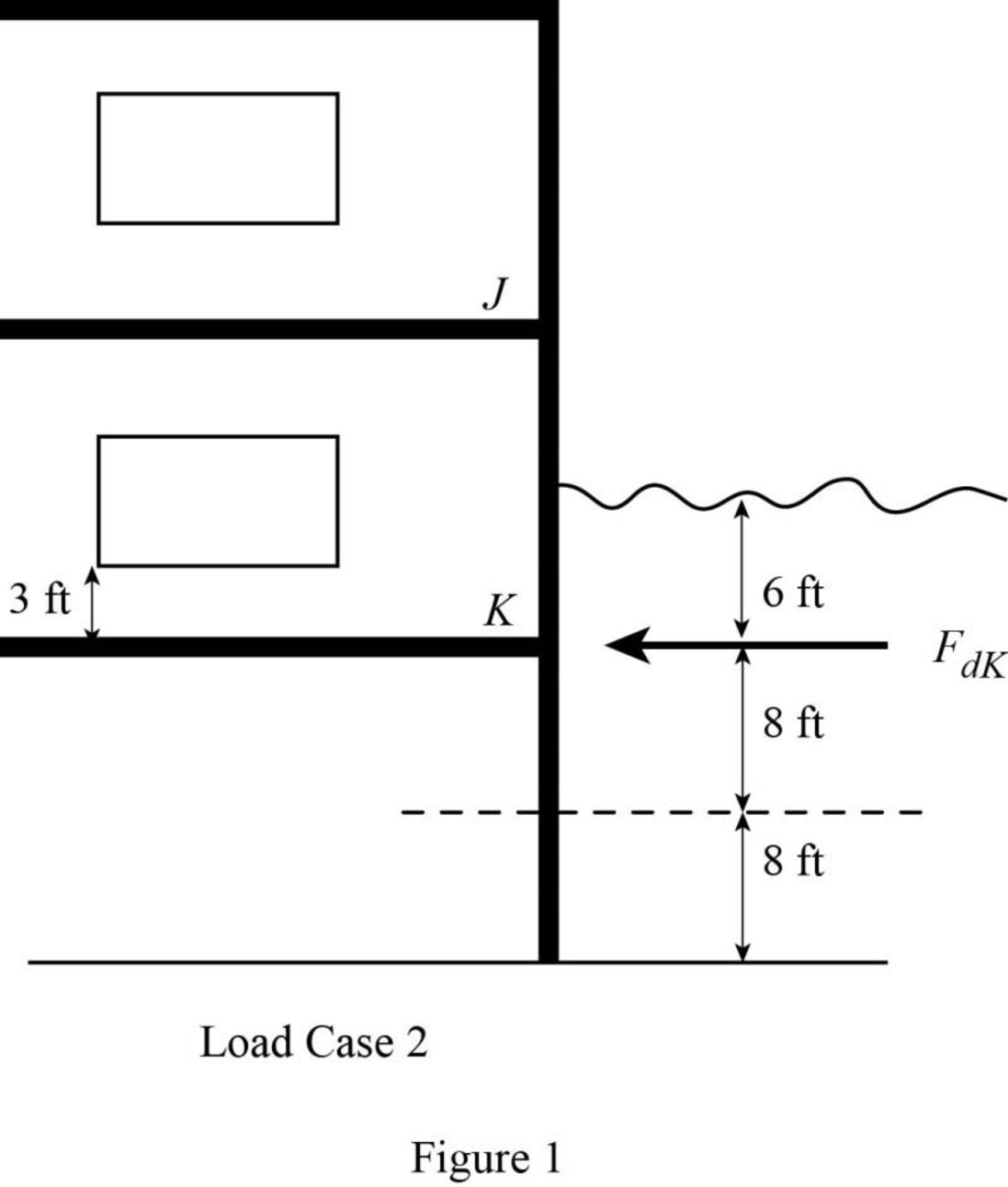
Refer to Figure 1.
Calculate the height of the water applicable to the structure for K as shown below.
Consider the specific weight density of sea water
Calculate the hydrodynamic load applied at floor level on the wall IJKL
Hence, the hydrodynamic load applied at floor level on the wall IJKL due to outflow for load case 2 is
For load case 3:
Calculate the height of the water applicable to the structure
Calculate the velocity of flow applicable to the structure
Sketch the load applied at floor level on the wall IJKL due to outflow for load case 3 as shown in Figure 2.
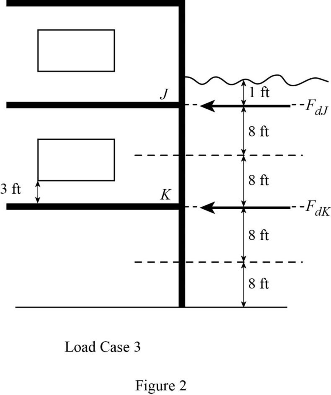
Refer to Figure 2.
Calculate the height of the water applicable to the structure for J as shown below.
Calculate the hydrodynamic load applied at floor level on the wall IJKL at J
Hence, the hydrodynamic load applied at floor level on the wall IJKL at J due to outflow for load case 3 is
Calculate the height of the water applicable to the structure for K as shown below.
Calculate the hydrodynamic load applied at floor level on the wall IJKL at K
Hence, the hydrodynamic load applied at floor level on the wall IJKL at K due to outflow for load case 3 is
Sketch the hydrostatic loading on the adjacent outside walls due to water retained by the floor as shown in Figure 3.
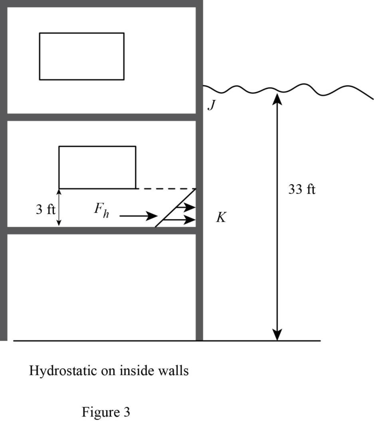
Refer to Figure 3.
Calculate the height of the water applicable to the structure
Calculate the hydrostatic loading on the adjacent outside walls due to water retained by the floor as shown below.
Hence, the hydrostatic loading on the adjacent outside walls due to water retained by the floor is
Consider the orientation coefficient
Calculate the debris impact load applied to the free standing column CD as shown below.
Therefore, the debris impact load applied to the free standing column CD is
Want to see more full solutions like this?
Chapter 2 Solutions
Fundamentals of Structural Analysis


- 54 7h de зк +F B + 8 8 Ө 6 A=Sin² E=290ooks for diagonal members A= 30.25in² E = 1800 ksi for hoizontal & Vertical members For Primary Structure revive roller@c, make Da roller and cut BF For redundant structures Redundant " " 2 склес しん Ik @D 3 14 @ BF しん ↑arrow_forwardA3.2- The 4.5m long cantilever beam is subjected to the specified uniformly distributed dead load 7.0 kN/m (including self-weight) and to the specified uniformly distributed live load 8.0 kN/m. The beam is made of normal density concrete containing maximum 20mm aggregate size with f'c = 25 MPa. Design the shear reinforcement for the beam using U-stirrups and fy = 400 MPa. Figure 2 WDL = 7.0 kN/m WLL=8.0 kN/m 4.5 m 450 mm' 380 mm *250 mm 3-30M Cross-sectionarrow_forwardA3.1- A simply supported beam is subjected to factored concentrated load of 400 kN at mid-span. The beam has a 10m span and a rectangular cross-section with bw = 350mm, effective depth d = 520mm, and total height h = 620mm. a) Ignor the self-weight of the beam and design the required shear reinforcement for the beam. Use 10M U-stirrups. b) Sketch the beam elevation and show the stirrups. Given: The beam is reinforced with 5-25M longitudinal bars f'c = 30 MPa fy = 400 MPa Maximum aggregate size: 20mm Figure 1 P= 400 kN k 5.0 m + 5.0 m 620 mm 520 mm 350 mm + Cross-sectionarrow_forward
- + 54 7h de зк +F 8 B 8 Ө 6 For Primary Structure remove and cut BF For redundant structures Redundant " " 2 склес しん Ik @D 3 14 @ BF しん ↑ A=Sin² E=290ooks for diagonal members A= 30.25in² E = 1800 ksi for hoizontal & Vertical members roller@G, make Da rollerarrow_forwardAn urban freeway is to be designed using the following information. AADT = 52,600 veh/day K (proportion of AADT occurring during the peak hour): D (proportion of peak hour traffic traveling in the peak direction): Trucks: 0.11 0.65 8% of peak hour volume PHF = 0.94 Lane width: Shoulder width: Total ramp density: Terrain: 12 ft 10 ft 0.5 interchange/mile; all interchanges are to be cloverleaf interchanges rolling Determine the number of lanes in the peak direction required to provide LOS C. (Assume commuter traffic and assume no RVs.) lanes Show all calculations required. (Calculate your answers for the peak direction only. Enter fy the peak hour volume in veh/h, the free flow speed in mi/h, the demand flow rate in pc/h/In, the mean speed in mi/h, and the density in pc/mi/In.) fHV peak hour volume free flow speed demand flow rate mean speed veh/h mi/h pc/h/In mi/h density pc/mi/Inarrow_forwardThe beam shown in the figure below is a W16 × 31 of A992 steel and has continuous lateral support. The two concentrated loads are service live loads. Neglect the weight of the beam and determine whether the beam is adequate. Suppose that P = 56 k. For W16 x 31: d=15.9 in., t = 0.275 in., h/t = 51.6, and M = M₁ = 203 ft-kip, M/ P P = = Mp/ =135 ft-kip. 6' W16 x 31 a. Use LRFD. Calculate the required moment strength, the allowable shear strength, and the maximum shear. (Express your answers to three significant figures.) = Mu QvVn Vu = = Beam is -Select- b. Use ASD. ft-kip kips kips Calculate the required moment strength, the allowable shear strength, and the maximum shear. (Express your answers to three significant figures.) Ma = Vn/b Va = = Beam is -Select- ft-kip kips kipsarrow_forward
- ***Please answer all parts. They are part of a single question and not different questions altogether. I will like the solution as well. Thank you!arrow_forwardConsider the geometric and traffic characteristics shown below. Approach (Width) Peak hour Approach Volumes: Left Turn Through Movement Right Turn Conflicting Pedestrian Volumes PHF For the following saturation flows: North (56 ft) South (56 ft) East (68 ft) West (68 ft) 165 105 200 166 442 395 585 538 162 157 191 200 900 1,200 1,200 900 0.95 0.95 0.95 0.95 Through lanes: 1,600 veh/h/in Through-right lanes: 1,400 veh/h/in Left lanes: 1,000 veh/h/in Left-through lanes: 1,200 veh/h/in Left-through-right lanes: 1,100 veh/h/in The total cycle length was 277 s. Now assume the saturation flow rates are 10% higher, that is, assume the following saturation flow rates: Through lanes: Through-right lanes: Left lanes: Left-through lanes: Left-through-right lanes: 1,760 veh/h/in 1,540 veh/h/in 1,100 veh/h/in 1,320 veh/h/in 1,210 veh/h/in Determine a suitable signal phasing system and phase lengths (in s) for the intersection using the Webster method. (Enter the sum of green and yellow times for…arrow_forwardDetermine the minimum of the appropriate yellow interval (Y . approach speed limit: 45 mi/h approach grade: 3.2% downgrade assumed perception-reaction time: 1.0 sec assumed deceleration rate: 11.2 ft/sec² assumed average vehicle length: 20 ft width of intersection to be crossed: 56 ft min' in s) for a signal phase under the following conditions.arrow_forward
- Compute the nominal shear strength of an M10 × 7.5 of A572 Grade 60 steel (Fy = 60 ksi). For M10 × 7.5: d = 9.99 in., tw = 0.13 in., h/tw Vn = x kips = 71.arrow_forwardA flexural member is fabricated from two flange plates 1/2 × 71/2 and a web plate 3/8 × 20. The yield stress of the steel is 50 ksi. a. Compute the plastic section modulus Z and the plastic moment Mp with respect to the major principal axis. (Express your answers to three significant figures.) Z = Mp = in. 3 ft-kips b. Compute the elastic section modulus S and the yield moment My with respect to the major principal axis. (Express your answers to three significant figures.) S = My = in.3 ft-kipsarrow_forwardThe beam shown in the figure below has lateral support at the ends only. The concentrated loads are live loads. Use A992 steel and select a shape. Do not check deflections. Use C = 1.0 (this is conservative). Suppose that PL = 20 k. PL PL Use the table below. Shape Mn Mn Vn Vn Ω Ων W12 × 58 216 144 132 87.8 W12 × 65 269 179 142 94.4 W12 × 72 308 205 159 106 W14 × 61 235 157 156 104 W14 × 68 280 187 174 116 W14 × 74 318 212 192 128 W16 × 67 276 184 193 129 18' a. Use LRFD. Calculate the factored-load moment (not including the beam weight). (Express your answer to three significant figures.) Mu = ft-kips Select a shape. -Select- b. Use ASD. Calculate the required flexural strength (not including the beam weight). (Express your answer to three significant figures.) Ma = Select a shape. -Select- ft-kipsarrow_forward

 Structural Analysis (10th Edition)Civil EngineeringISBN:9780134610672Author:Russell C. HibbelerPublisher:PEARSON
 Principles of Foundation Engineering (MindTap Cou...Civil EngineeringISBN:9781337705028Author:Braja M. Das, Nagaratnam SivakuganPublisher:Cengage Learning
 Fundamentals of Structural AnalysisCivil EngineeringISBN:9780073398006Author:Kenneth M. Leet Emeritus, Chia-Ming Uang, Joel LanningPublisher:McGraw-Hill Education
 Traffic and Highway EngineeringCivil EngineeringISBN:9781305156241Author:Garber, Nicholas J.Publisher:Cengage Learning