Loading diagram for the members BE and FED.
Answer to Problem 2.1P
Explanation of Solution
Given information:
Concept used:
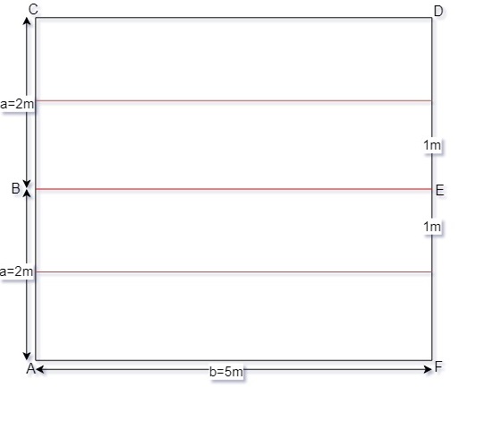
One-way slab is a slab which is supported by beams on two opposite sides to carry the load along one direction. In one way slab, the ratio of longer span (b) to shorter span (a) is equal or greater than 2.
Calculation:
Beam BE:
Since
Thus, the tributary area for this beam is rectangular as shown in Fig. (a) and the intensity of the uniformly distributed load is as follows:
Dead load for 200mm concrete slab
Live load for office
Total uniform distributed load
Due to symmetry the vertical reactions at B and E are
The loading diagram for beam BE is shown in Fig. (b)
Beam FED:
The load supported by this beam is the vertical reaction of beam BE at E which is
The loading diagram for this beam is shown below:
Fig. (a)
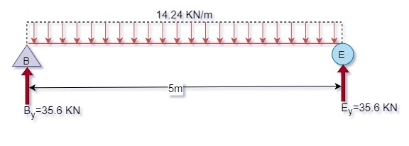
Fig. (b)
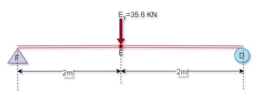
Fig. (c)
Conclusion:
The loading diagrams are shown in the figures above and it is a one-way slab.
Want to see more full solutions like this?
Chapter 2 Solutions
Structural Analysis, Student Value Edition Plus Mastering Engineering With Pearson Etext -- Access Card Package (10th Edition)

- 5-1. Determine the force in each member of the truss, and state if the members are in tension or compression.arrow_forwardI have the correct answer provided, just lookng for a more detailed breadown of how the answer was obtained thanks.arrow_forwardQ1. Statically indeterminate beam analysis. a) Calculate the BMs (bending moments) at all the joints of the beam shown in Fig.1 using the moment distribution method. The beam is subjected to an UDL of w kN/m. L1= 0.4L. Assume the support at C is pinned, and A and B are roller supports. E = 200 GPa, I=250x106 mm². Use the values of w = 50 kN/m and L = 6 b) Draw the shear force and bending diagrams for the entire beam. c) Calculate the BMs at all the joints of the same beam shown in Fig.1 using the slope deflection method. d) Compare the values of BMs obtained using the two methods a) and c) and comment. w kN/m £1m Lm m Fig 1. Beam for Q1arrow_forward
- I have the answer provided for the question, just looking for a more detailed breadown of how it was obtained thanks.arrow_forwardQ5.--Finite-element-modelling. a) → Draw-a-2D-element-and-show-the dots (degrees of freedom). Draw-all-the-2D-elements. used-in-Strand 7..Explain the differences between-these-elements-in-terms-of-the-no..of. nodes-and-interpolation/shape-functions used. b)→A-8-m-x-8-m-plate (in-the-xx-plane)-with-8-mm-thickness, is fixed-at-all-the-edges.and.is. loaded-by-a-pressure-loading-of-4 kN/m2.-in-the-downward-(-2)-direction.-The-plate.is. made-of-steel-(E=-200 GPa, density-7850-kg/m3). Explain-the-steps-involved-in-setting. up-a-Strand 7-model-for-this-problem. Your-explanation-should-include-how-the-given. input-data-for-this-problem-will-be-used-in-Strand 7-modelling. Explain how you would. determine the maximum-deflection-from-the-Strand 7-output.-1 11arrow_forwardI need Help some hw for AutoCAD please use measure front top and side viewarrow_forward
- Calculate the discharge of the system shown below. Neglecting minor losessarrow_forwardQ3. Statically determinate or indeterminate beam analysis by the stiffness method a) Determine the global stiffness matrix of the beam shown in Fig. 3. Assume supports at 1 and 3 are rollers and the support at 2 is a pinned support. Indicate the degrees- of freedom in all the stiffness matrices. El is constant. Use the values of w = 50 kN/m and L1 = 2.0 m Note, L2-3L1. b) Determine the rotations at all the nodes of the beam and reactions at the supports. Show all calculations. c) Draw the BMD of the beam on the compression side showing the salient values. What are the maximum bending moments of the beam? Draw the deflected shape of the beam. d) Solve the problem using the Strand7. Assume any suitable value of El (state the value you have used for El). Show the model with all the nodes, element numbers and boundary conditions. Display the deflected shape and BMD. e) Show a table comparing the stiffness method (manual calculations) of the all the reactions and the maximum bending moment…arrow_forwardUsing AutoCAD. I need help please to exact measurearrow_forward
- Draw Isometric view of this multiview of object.arrow_forwardREMINDER: The truss must be cut into two different sections. You can choose either one to solve as you will get the same answer. Since there are three equations available, you can't cut more than three members 6.25 Determine the force in members BD, CD, and CE of the truss shown. BO C 36 kips 36 kips D F H 7.5 ft E G 4 panels at 10 ft = 40 ftarrow_forwardCalculate the area of the following polygon using the abscissa and projection method, taking into account the necessary adjustments before calculating the area of the polygon using the compass rule. Latitude Departure Side 930.63 N 930.63 S 1272 E 1271 W AB 122.14 E=12/2-1271-1 cr=-1 680 BC 173.83 length 591 CD 669.13 109.08 DE 139.36 961.1 EA 756.80 201.82 330.63/ 430.65 DEP=L SIN (O) >L DEP/SIN(O) LAT = L COS (0) DEPILATESIN(OYCOS (0)= TAN (0) O TAN-1 (DEP/LAT)= asztan Deptarrow_forward

 Structural Analysis (10th Edition)Civil EngineeringISBN:9780134610672Author:Russell C. HibbelerPublisher:PEARSON
 Principles of Foundation Engineering (MindTap Cou...Civil EngineeringISBN:9781337705028Author:Braja M. Das, Nagaratnam SivakuganPublisher:Cengage Learning
 Fundamentals of Structural AnalysisCivil EngineeringISBN:9780073398006Author:Kenneth M. Leet Emeritus, Chia-Ming Uang, Joel LanningPublisher:McGraw-Hill Education
 Traffic and Highway EngineeringCivil EngineeringISBN:9781305156241Author:Garber, Nicholas J.Publisher:Cengage Learning