
Concept explainers
Videos
A person gets in an elevator on the ground floor and rides it to the top floor of a building. Sketch a velocity-versus-time graph for this motion.
To draw: The velocity-versus-time graph.
Answer to Problem 1CQ
The velocity-versus-time graph is drawn.
Explanation of Solution
Given data:
A person gets in an elevator on the ground floor and rides it to the top floor of a building.
Explanation:
Normally when the elevator starts to function, initially the speed or velocity will be low and then gradually increases its speed. In the middle period of the elevator functioning, the speed becomes constant and at end period speed slows down and comes to rest.
The velocity-versus-time graph for the above scenario is shown in Figure 1.
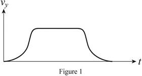
Initially graph starts from zero, gradually increases. During middle period velocity remains constant showing horizontal line in the graph. During end period there will be gradual decrease and end at zero in the graph.
Conclusion:
Hence, the velocity-versus-time graph is drawn.
Want to see more full solutions like this?
Chapter 2 Solutions
College Physics: A Strategic Approach (4th Edition)
Additional Science Textbook Solutions
Human Biology: Concepts and Current Issues (8th Edition)
Genetic Analysis: An Integrated Approach (3rd Edition)
Physics for Scientists and Engineers: A Strategic Approach, Vol. 1 (Chs 1-21) (4th Edition)
Chemistry: An Introduction to General, Organic, and Biological Chemistry (13th Edition)
Microbiology: An Introduction
Campbell Biology (11th Edition)


- Shrinking Loop. A circular loop of flexible iron wire has an initial circumference of 161 cm , but its circumference is decreasing at a constant rate of 15.0 cm/s due to a tangential pull on the wire. The loop is in a constant uniform magnetic field of magnitude 1.00 T , which is oriented perpendicular to the plane of the loop. Assume that you are facing the loop and that the magnetic field points into the loop. Find the magnitude of the emf E induced in the loop after exactly time 9.00 s has passed since the circumference of the loop started to decrease. Find the direction of the induced current in the loop as viewed looking along the direction of the magnetic field. Please explain all stepsarrow_forwardA circular loop of wire with radius 0.0480 m and resistance 0.163 Ω is in a region of spatially uniform magnetic field, as shown in the following figure (Figure 1). The magnetic field is directed out of the plane of the figure. The magnetic field has an initial value of 7.88 T and is decreasing at a rate of -0.696 T/s . Is the induced current in the loop clockwise or counterclockwise? What is the rate at which electrical energy is being dissipated by the resistance of the loop? Please explain all stepsarrow_forwardA 0.333 m long metal bar is pulled to the left by an applied force F and moves to the left at a constant speed of 5.90 m/s. The bar rides on parallel metal rails connected through a 46.7 Ω resistor, as shown in (Figure 1), so the apparatus makes a complete circuit. You can ignore the resistance of the bar and rails. The circuit is in a uniform 0.625 T magnetic field that is directed out of the plane of the figure. Is the induced current in the circuit clockwise or counterclockwise? What is the rate at which the applied force is doing work on the bar? Please explain all stepsarrow_forward
- A 0.850-m-long metal bar is pulled to the right at a steady 5.0 m/s perpendicular to a uniform, 0.650-T magnetic field. The bar rides on parallel metal rails connected through a 25-Ω, resistor (Figure 1), so the apparatus makes a complete circuit. Ignore the resistance of the bar and the rails. Calculate the magnitude of the emf induced in the circuit. Find the direction of the current induced in the circuit. Calculate the current through the resistor.arrow_forwardIn the figure, a conducting rod with length L = 29.0 cm moves in a magnetic field B→ of magnitude 0.510 T directed into the plane of the figure. The rod moves with speed v = 5.00 m/s in the direction shown. When the charges in the rod are in equilibrium, which point, a or b, has an excess of positive charge and where does the electric field point? What is the magnitude E of the electric field within the rod, the potential difference between the ends of the rod, and the magnitude E of the motional emf induced in the rod? Which point has a higher potential? Please explain all stepsarrow_forwardExamine the data and % error values in Data Table 2 where the mass of the pendulum bob increased but the angular displacement and length of the simple pendulum remained constant. Describe whether or not your data shows that the period of the pendulum depends on the mass of the pendulum bob, to within a reasonable percent error.arrow_forward
- Please graph, my software isn't working - Data Table 4 of Period, T vs √L . (Note: variables are identified for graphing as y vs x.) On the graph insert a best fit line or curve and display the equation on the graph. Thank you!arrow_forwardI need help with problems 93 and 94arrow_forwardSince the instruction says to use SI units with the correct sig-fig, should I only have 2 s for each trial in the Period column? Determine the theoretical period of the pendulum using the equation T= 2π √L/g using the pendulum length, L, from Data Table 2. Calculate the % error in the periods measured for each trial in Data Table 2 then recordarrow_forward
- A radiography contingent are carrying out industrial radiography. A worker accidentally crossed a barrier exposing themselves for 15 seconds at a distance of 2 metres from an Ir-192 source of approximately 200 Bq worth of activity. What dose would they have received during the time they were exposed?arrow_forwardIn the following figure the circuit to the left has a switch thatat t = 0 s is switched and disconnects the battery from the circuit. The state depicted on thefigure is right after the switch, still t = 0. As the current decreases over time, the magneticflux through the circuit on the right (due to the long cable of the circuit on the left) changesand induces an EMF on the right circuit. How much power is consumed by R2 as a functionof time.The distance between the wire on the left and the closest wire on the right is r = 2.0 cm.The size of the circuit on the right is noted on the figure.arrow_forwardsingly A samply ionized helium atom is in the ground state. It absorbs energy and makes a transition to the n=7 excited state. The ion returns to wo the wavelength the ground state by emitting SIX photons ONLY. What is the of the second highest energy photon ?arrow_forward
 Principles of Physics: A Calculus-Based TextPhysicsISBN:9781133104261Author:Raymond A. Serway, John W. JewettPublisher:Cengage Learning
 Physics for Scientists and EngineersPhysicsISBN:9781337553278Author:Raymond A. Serway, John W. JewettPublisher:Cengage Learning
 Physics for Scientists and Engineers with Modern ...PhysicsISBN:9781337553292Author:Raymond A. Serway, John W. JewettPublisher:Cengage Learning
 Physics for Scientists and Engineers, Technology ...PhysicsISBN:9781305116399Author:Raymond A. Serway, John W. JewettPublisher:Cengage Learning
 University Physics Volume 1PhysicsISBN:9781938168277Author:William Moebs, Samuel J. Ling, Jeff SannyPublisher:OpenStax - Rice University
 College PhysicsPhysicsISBN:9781305952300Author:Raymond A. Serway, Chris VuillePublisher:Cengage Learning