Videos
Two distances are required to specify the location of a point relative to an origin in two-dimensional space (Fig. P2.14):
The horizontal and vertical distances
The radius and angle
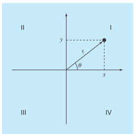
FIGURE P2.14
It is relatively straight forward to compute Cartesian coordinates
If the coordinates lie within the first and fourth coordinates
The difficulty arises for the other cases. The following table summarizes the possibilities:
| x | Y |
|
|
|
|
|
|
|
|
|
|
|
|
|
|
|
|
|
|
|
|
|
|
|
|
0 |
(a) Write a well-structured flowchart for a subroutine procedure to calculate r and
(b) Write a well-structured function procedure based on your flowchart. Test your program by using it to fill out the following table:
| x | Y | r |
|
| 1 | 0 | ||
| 1 | 1 | ||
| 0 | 1 | ||
| –1 | 1 | ||
| –1 | 0 | ||
| –1 | –1 | ||
| 0 | –1 | ||
| 1 | –1 | ||
| 0 | 0 |
(a)
A well-structured flowchart for a subordinate procedure to calculate r and
Answer to Problem 14P
Solution:

Explanation of Solution
Given Information:
To specify the location of a point relative to origin, cartesian coordinates
Cartesian coordinates can be easily computed from the polar coordinates.
Polar coordinates are computed as follows:
Formula used:
Calculation:
The flowchart for converting from Cartesian to polar coordinates is as follows
(b)
A well-structured function procedure based on flowchart of part (a) if two distances are required to specify the location of a point relative to an origin in two-dimensional space. Also, test the program by filling the table given below:
Answer to Problem 14P
Solution:
The values of r and
Explanation of Solution
Given Information:
To specify the location of a point relative to origin, cartesian coordinates
Cartesian coordinates can be easily computed from the polar coordinates.
Polar coordinates are computed as follows:
Calculation:
The MATLAB program for converting Cartesian to polar coordinates is as follows:
% Define a function polar()
function polar(x, y)
% Formula to calculate r
r = sqrt (x.^ 2+ y.^ 2);
if x > 0
% Formula to calculate theta
th= atan(y/ x);
elseif x < 0
% Use for loop to check the condition
if y > 0
th= atan(y / x)+ pi;
elseif y < 0
th= atan(y / x)- pi;
else
th= pi;
end
else
if y > 0
th= pi / 2;
elseif y < 0
th=- pi / 2;
else
th= 0;
end
end
theta = th* 180 / pi;
% Display the polar coordinates
fprintf('r = %4.4f theta = %4.2f\n',r,theta);
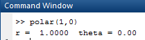
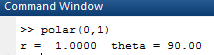
Now, to test the program use the following command.
First find polar coordinates for
OUTPUT:
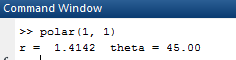
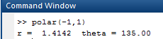
Now, for polar coordinates for
OUTPUT:
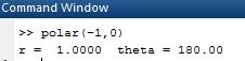
Now, for polar coordinates for
OUTPUT:
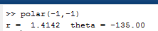
Now, forpolar coordinates for
OUTPUT:
Now, forpolar coordinates for
OUTPUT:
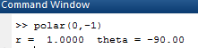
Now, forpolar coordinates for
OUTPUT:
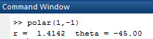
Now, forpolar coordinates for
OUTPUT:
Now, forpolar coordinates for
OUTPUT:
Now, forpolar coordinates for
OUTPUT:
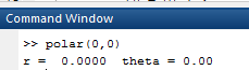
Hence, the values of r and
Want to see more full solutions like this?
Chapter 2 Solutions
EBK NUMERICAL METHODS FOR ENGINEERS
Additional Engineering Textbook Solutions
Pathways To Math Literacy (looseleaf)
Math in Our World
Intermediate Algebra (13th Edition)
APPLIED STAT.IN BUS.+ECONOMICS


- Use the Euclidean algorithm to find two sets of integers (a, b, c) such that 55a65b+143c: Solution = 1. By the Euclidean algorithm, we have: 143 = 2.65 + 13 and 65 = 5.13, so 13 = 143 – 2.65. - Also, 55 = 4.13+3, 13 = 4.3 + 1 and 3 = 3.1, so 1 = 13 — 4.3 = 13 — 4(55 – 4.13) = 17.13 – 4.55. Combining these, we have: 1 = 17(143 – 2.65) - 4.55 = −4.55 - 34.65 + 17.143, so we can take a = − −4, b = −34, c = 17. By carrying out the division algorithm in other ways, we obtain different solutions, such as 19.55 23.65 +7.143, so a = = 9, b -23, c = 7. = = how ? come [Note that 13.55 + 11.65 - 10.143 0, so we can obtain new solutions by adding multiples of this equation, or similar equations.]arrow_forward- Let n = 7, let p = 23 and let S be the set of least positive residues mod p of the first (p − 1)/2 multiple of n, i.e. n mod p, 2n mod p, ..., p-1 2 -n mod p. Let T be the subset of S consisting of those residues which exceed p/2. Find the set T, and hence compute the Legendre symbol (7|23). 23 32 how come? The first 11 multiples of 7 reduced mod 23 are 7, 14, 21, 5, 12, 19, 3, 10, 17, 1, 8. The set T is the subset of these residues exceeding So T = {12, 14, 17, 19, 21}. By Gauss' lemma (Apostol Theorem 9.6), (7|23) = (−1)|T| = (−1)5 = −1.arrow_forwardLet n = 7, let p = 23 and let S be the set of least positive residues mod p of the first (p-1)/2 multiple of n, i.e. n mod p, 2n mod p, ..., 2 p-1 -n mod p. Let T be the subset of S consisting of those residues which exceed p/2. Find the set T, and hence compute the Legendre symbol (7|23). The first 11 multiples of 7 reduced mod 23 are 7, 14, 21, 5, 12, 19, 3, 10, 17, 1, 8. 23 The set T is the subset of these residues exceeding 2° So T = {12, 14, 17, 19, 21}. By Gauss' lemma (Apostol Theorem 9.6), (7|23) = (−1)|T| = (−1)5 = −1. how come?arrow_forward
- Shading a Venn diagram with 3 sets: Unions, intersections, and... The Venn diagram shows sets A, B, C, and the universal set U. Shade (CUA)' n B on the Venn diagram. U Explanation Check A- B Q Search 田arrow_forwardWhat is the area of this figure? 5 mm 4 mm 3 mm square millimeters 11 mm Submit 8 mm Work it out 9 mmarrow_forwardPlease explain how come of X2(n).arrow_forward
- No chatgpt pls will upvotearrow_forwardFind all solutions of the polynomial congruence x²+4x+1 = 0 (mod 143). (The solutions of the congruence x² + 4x+1=0 (mod 11) are x = 3,4 (mod 11) and the solutions of the congruence x² +4x+1 = 0 (mod 13) are x = 2,7 (mod 13).)arrow_forwardDetermine whether each function is an injection and determine whether each is a surjection.The notation Z_(n) refers to the set {0,1,2,...,n-1}. For example, Z_(4)={0,1,2,3}. f: Z_(6) -> Z_(6) defined by f(x)=x^(2)+4(mod6). g: Z_(5) -> Z_(5) defined by g(x)=x^(2)-11(mod5). h: Z*Z -> Z defined by h(x,y)=x+2y. j: R-{3} -> R defined by j(x)=(4x)/(x-3).arrow_forward
- Determine whether each function is an injection and determine whether each is a surjection.arrow_forwardLet A = {a, b, c, d}, B = {a,b,c}, and C = {s, t, u,v}. Draw an arrow diagram of a function for each of the following descriptions. If no such function exists, briefly explain why. (a) A function f : AC whose range is the set C. (b) A function g: BC whose range is the set C. (c) A function g: BC that is injective. (d) A function j : A → C that is not bijective.arrow_forwardLet f:R->R be defined by f(x)=x^(3)+5.(a) Determine if f is injective. why?(b) Determine if f is surjective. why?(c) Based upon (a) and (b), is f bijective? why?arrow_forward
 Algebra & Trigonometry with Analytic GeometryAlgebraISBN:9781133382119Author:SwokowskiPublisher:Cengage
 Trigonometry (MindTap Course List)TrigonometryISBN:9781337278461Author:Ron LarsonPublisher:Cengage Learning