
Concept explainers
Videos
The crude-oil pumping rig shown is driven at 20 rpm. The inside diameter of the well pipe is 2 in., and the diameter of the pump rod is 0.75 in. The length of the pump rod and the length of the column of oil lifted during the stroke are essentially the same, and equal to 6000 ft. During the downward stroke, a valve at the lower end of the pump rod opens to let a quantity of oil into the well pipe, and the column of oil is then lifted to obtain a discharge into the connecting pipeline. Thus, the amount of oil pumped in a given time depends upon the stroke of the lower end of the pump rod. Knowing that the upper end of the rod at D is essentially sinusoidal with a stroke of 45 in. and the specific weight of crude oil is 56.2 lb/ft3, determine (a) the output of the well in ft3/min if the shaft is rigid, (b) the output of the well in ft3/min if the stiffness of the rod is 2210 N/m, the equivalent mass of the oil and shaft is 290 kg, and damping is negligible.
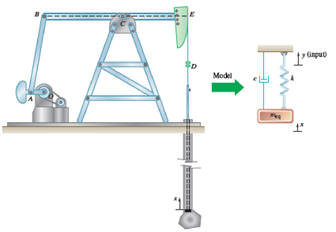
Fig. P19.108
Want to see the full answer?
Check out a sample textbook solution
Chapter 19 Solutions
Vector Mechanics for Engineers: Statics and Dynamics


- HW8 A shaft fitted with a flywheel rotates at 650 r.p.m. and drives a machine. The torque of machine varies in a cyclic manner over a period of 2 revolutions. The torque rises from 650 N-m to 2200 N-m uniformly during 110° and remains constant for the following 270°. It then falls uniformly to 600 N-m during the next 100° and remains constant for the end cycle, the cycle being repeated thereafter. Determine the power required to drive the machine and percentage fluctuation in speed, if the driving torque applied to the shaft is constant and the mass of the flywheel is 180 kg with radius of gyration of 35 cm. HW9arrow_forwardunits of h. show all workarrow_forward4. Steam flows steadily through a turbine at a rate of 47,000 lbm/h, entering at 1000 psia and 800°F and leaving at 6 psia as saturated vapor. If the power generated by the turbine is 3.7 MW, determine the rate of heat loss from the steam.arrow_forward
- 3. Water enters the constant 125-mm inside-diameter tubes of a boiler at 7.5 MPa and 60°C and leaves the tubes at 6 MPa and 500°C with a velocity of 75 m/s. Calculate the velocity of the water at the tube inlet and the inlet volume flow rate.arrow_forward2. A piston-cylinder device contains 2.4 kg of nitrogen initially at 120 kPa and 27°C. The nitrogen is now compressed slowly in a polytropic process during which PV1.3 = constant until the volume is reduced by one-half. Determine the work done and the heat transfer for this process.arrow_forward1. 1.25 m³ of saturated liquid water at 225°C is expanded isothermally in a closed system until its quality is 75 percent. Determine the total work produced by this expansion, in kJ.arrow_forward
- An undamped single-degree-of-freedom system is subjected to dynamic excitation as shown in Figure 1.• System properties: m = 1, c = 0, k = (6π)2.• Force excitation: p(t) = posin(ωt) where po = 9 and ω = 2π.• Initial conditions: u(t = 0) = 0 and ̇u(t = 0) = 0.Please, complete Parts (a) through (d) using any computational tool of your preference. The preferred toolis MATLAB. Print and turn in a single pdf file that will include your code/calculations and your plots.(a) Generate the solution using a linear interpolation of the load over each time step (note that hereyou can use the undamped coefficients). Plot the displacement response for the first 4 seconds andcompare to the exact closed form solution. Repeat using the following time step sizes, ∆t = 0.01,0.05, 0.15, 0.20 seconds. Include the closed form solution and the solutions for different ∆t values in asingle plot. Please, provide your observations by comparing the closed form solution with the solutionsderived using the four…arrow_forwardAssume multiple single degree of freedom systems with natural periods T ∈ [0.05, 2.00] seconds with in-crement of period dT = 0.05 seconds. Assume three cases of damping ratio: Case (A) ξ = 0%; Case (B)ξ = 2%; Case (C) ξ = 5%. The systems are initially at rest. Thus, the initial conditions are u(t = 0) = 0 anḋu(t = 0) = 0. The systems are subjected to the base acceleration that was provided in the ElCentro.txt file(i.e., first column). For the systems in Case (A), Case (B), and Case (C) and for each natural period computethe peak acceleration, peak velocity, and peak displacement responses to the given base excitation. Please,use the Newmark method for β = 1/4 (average acceleration) to compute the responses. Create threeplots with three lines in each plot. The first plot will have the peak accelerations in y-axis and the naturalperiod of the system in x-axis. The second plot will have the peak velocities in y-axis and the natural periodof the system in x-axis. The third plot will have…arrow_forwardBoth portions of the rod ABC are made of an aluminum for which E = 70 GPa. Based on the given information find: 1- deformation at A 2- stress in BC 3- Total strain 4- If v (Poisson ratio is 0.25, find the lateral deformation of AB Last 3 student ID+ 300 mm=L2 724 A P=Last 2 student ID+ 300 KN 24 24 Diameter Last 2 student ID+ 15 mm Last 3 student ID+ 500 mm=L1 724 C B 24 Q=Last 2 student ID+ 100 KN 24 Diameter Last 2 student ID+ 40 mmarrow_forward
- Q2Two wooden members of uniform cross section are joined by the simple scarf splice shown. Knowing that the maximum allowable tensile stress in the glued splice is 75 psi, determine (a) the largest load P that can be safely supported, (b) the corresponding shearing stress in the splice. น Last 1 student ID+5 inch=W =9 4 L=Last 1 student ID+8 inch =12 60° P'arrow_forwardQ4 The two solid shafts are connected by gears as shown and are made of a steel for which the allowable shearing stress is 7000 psi. Knowing the diameters of the two shafts are, respectively, dBC determine the largest torque Tc that can be applied at C. 4 and dEF dBC=Last 1 student ID+3 inch dEF=Last 1 student ID+1 inch 7 R=Last 1 Student ID+5 inch 9 R B Tc 2.5 in. E TF Harrow_forwardExperiment تكنولوجيا السيارات - Internal Forced convenction Heat transfer Air Flow through Rectangular Duct. objective: Study the convection heat transfer of air flow through rectangular duct. Valve Th Top Dead Centre Exhaust Valve Class CP. N; ~ RIVavg Ti K 2.11 Te To 18.8 21.3 45.8 Nath Ne Pre Calculations:. Q = m cp (Te-Ti) m: Varg Ac Acca*b Q=hexp As (Ts-Tm) 2 2.61 18.5 20.846.3 Tm = Te-Ti = 25 AS-PL = (a+b)*2*L Nu exp= Re-Vavy D heep Dh k 2ab a+b Nu Dh the- (TS-Tm) Ts. Tmy Name / Nu exp Naxe بب ارتدان العشريarrow_forward
 Elements Of ElectromagneticsMechanical EngineeringISBN:9780190698614Author:Sadiku, Matthew N. O.Publisher:Oxford University Press
 Mechanics of Materials (10th Edition)Mechanical EngineeringISBN:9780134319650Author:Russell C. HibbelerPublisher:PEARSON
 Thermodynamics: An Engineering ApproachMechanical EngineeringISBN:9781259822674Author:Yunus A. Cengel Dr., Michael A. BolesPublisher:McGraw-Hill Education
 Control Systems EngineeringMechanical EngineeringISBN:9781118170519Author:Norman S. NisePublisher:WILEY
 Mechanics of Materials (MindTap Course List)Mechanical EngineeringISBN:9781337093347Author:Barry J. Goodno, James M. GerePublisher:Cengage Learning
 Engineering Mechanics: StaticsMechanical EngineeringISBN:9781118807330Author:James L. Meriam, L. G. Kraige, J. N. BoltonPublisher:WILEY