
Concept explainers
The structural components of a flexible pavement.
Explanation of Solution
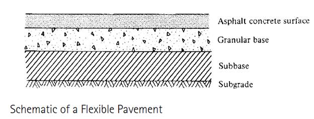
The structural components of a flexible pavement are as follows:
- The subgrade or prepared roadbed,
- The subbase,
- The base and
- The surface course.
It is necessary to check for the evaluation of every component of the flexible pavement and
Subgrade (Prepared Roadbed)
It is first in the line of materials that are to be laid and serves as the foundation of the flexible pavement structure. It is being spread along the horizontal alignment of the pavement. The materials used in this layer are very well compacted to meet the prescribed specifications of strength. In this layer, borrow materials may also be used according to the pavement being constructed.
Subbase Course
This layer is kept above the subgrade and the materials used in this layer are of better quality as compared to that of the materials used in subgrade. The materials used in this flexible pavement structure must meet the specifications in terms of gradation, strength and plastic characteristics.
And in case, if the materials for the subbase course aren't readily available then the subgrade materials are treated to meet the specifications that of the subbase course material properties.
Base Course
This course comes at the third place in the line of pavement structures. It isplaced just above the subbase course and if subbase is not used then it lies immediately above the subgrade of the pavement structure. The materials that are used in this pavement section are of much better quality then those used in the previous layers in terms of gradation, strength and plastic requirements. Granular materials likestone,slag, gravel, and sand are used in this course of flexible pavement structure.Wherein, slag and gravel can be used in both forms i.e., (crushed or uncrushed) stones should be crushed. In case if some of the materials are not meeting the specifications for this line of course then they are used in the base if appropriately stabilized with Portland cement, lime or asphalt.For high quality pavements the material is treated with Portland cement or asphalt to improve the stiffness characteristics of such pavements.
Surface Course
This is the topmost layer of the flexible pavement and is placed above the base course of the road pavement. The materials in this pavement include a mixture of aggregates and asphalt. The properties of this material must be able to hold out against the high tire pressure, withstand abrasive forces due to the traffic flow, prevention against the infiltration of surface water to avoid rupturing of surface course and weakening of the underlying structural bed of the pavement. Considering the expected traffic flow the thickness of this layer varies from 3 inches to 6 inches.
Want to see more full solutions like this?


- Estimate the material quantities (cement, sand, gravel, and steel reinforcement) required for constructing 120 m concrete channel of the following typical cross section, concrete mix of 1:1.5:3 and thickness of 20 cm. Figure (1) Figure (1) 12250- 16300arrow_forwarda) A 14-ft. tall and12-ft.-8-in. long fully grouted reinforced masonry wall is constructed of 8-in.CMU. It is to be analyzed for out-of-plane loading. Construct thenP -nM curves for the wallwith the following three vertical reinforcement scenarios: (1) 10 No. 6 bars at 16 in. spacing,(2) 10 No. 5 bars at 16 in. spacing, and (3) 7 No. 4 bars at 24 in. spacing. The steel is Grade60 with a modulus of elasticity of 29,000 ksi, and the masonry has a compressive strength of2,000 psi. You may use Excel or Matlab to construct the curves. Also, show the maximumnPallowed by the code for each case.(b) For each of the above reinforcement scenarios, determine the maximum axial loads that arepermitted for the tension-controlled condition and transition condition.(c) Discuss how the amount of vertical reinforcement affects thenPn-Mn curve.arrow_forwardYOU HAVE SET YOUR LEVEL UP AND ARE UTILIZING CP-101 ELEVATION FOR YOUR BENCHMARK AND HAVE THE FOLLOWING READING:CP-101=6.02YOUR FORM ELEVATION READINGS ("ATTACHED")( BEGINNING AT THE NORTHEAST BUILDING CORNER)AND WORKING IN A CLOCKWISE DIRECTION CHECKING THE BUILDING CORNER FORMSARE AS FOLLOWS: (CALCULATE THE ELEVATIONS OF 1-6 BELOW) 1. NE COR. = 1.152. SE COR. = 1.153. SW COR. = 1.354. (N) SW COR. = 1.155. INTERIOR = 1.306. NW COR. = 1.15arrow_forward
- a) A 14-ft. tall and12-ft.-8-in. long fully grouted reinforced masonry wall is constructed of 8-in.CMU. It is to be analyzed for out-of-plane loading. Construct thenP -nM curves for the wallwith the following three vertical reinforcement scenarios: (1) 10 No. 6 bars at 16 in. spacing,(2) 10 No. 5 bars at 16 in. spacing, and (3) 7 No. 4 bars at 24 in. spacing. The steel is Grade60 with a modulus of elasticity of 29,000 ksi, and the masonry has a compressive strength of2,000 psi. You may use Excel or Matlab to construct the curves. Also, show the maximumnPallowed by the code for each case.(b) For each of the above reinforcement scenarios, determine the maximum axial loads that arepermitted for the tension-controlled condition and transition condition.(c) Discuss how the amount of vertical reinforcement affects thenPn - Mn curve.arrow_forwardIf you could help me answer these questions in matlab that would be great, I provided an additional picture detailing what the outcome should look like.arrow_forwardA fully grouted reinforced masonry wall is to be constructed of 8-in. CMU. The wall height is 18feet. It is assumed to be simply supported. The wall is to be designed for an out-of-plane seismicload of 52 lbs./ft.2, which can act in either direction. The wall also supports a roof dead load of600 lbs./ft. and a roof live load of 300 lbs./ft. along the wall length. The roof loads have aneccentricity of 2.5 inches. Since there is seismic load, load combinations (6) and (7) in Chapter 2of ASCE 7-22 should be considered. In these two load combinations,horizontal seismic loadhE =andvertical seismic loadvE = . You may ignorevE in this problem for simplicity. The masonryhas a specified compressive strength of 2,500 psi. (a) Use the strength design provisions of TMS402 to determine the size and spacing of the vertical bars needed. Use the P-δ analysis method inSection 9.3.4.4.2 of TMS 402 to determine Mu. (b) Repeat the design using the momentmagnification method in Section 9.3.4.4.3 instead.arrow_forward
- The factor of safety for tipping of the concrete dam is defined as the ratio of the stabilizing moment due to the dam's weight divided by the overturning moment about OO due to the water pressure (Figure 1). Suppose that aa = 5 mm , dd = 2 mm , hh = 7 mm . The concrete has a density of ρconcρconc = 2.5 Mg/m3Mg/m3 and for water ρwρw = 1 Mg/m3Mg/m3arrow_forwardcan you answer both plss, i will give u a likearrow_forward*1-4. The hollow core panel is made from plain stone concrete. Determine the dead weight of the panel. The holes each have a diameter of 100 mm. 200 mm 300 mm 300 mm 300 mm 300 mm 300 mm Prob. 1-4 300 mm 4 marrow_forward
- derive the expressions for V and M, and draw the shear forceandbendingmomentdiagrams.Neglecttheweightofthebeam.arrow_forwarda. Draw trajectories of approximately 8 to 11 vehicles moving on a one way 1-lane road with different time-varying speeds. b. Consider a time-space window in the time-space diagram of part (a). See below. Denote the number of vehicles passing BD, DC, AC, and AB respectively as n1, N2, N3, and n4. Write an equation relating n₁, N2, N3, and n4 to each other. What is the physical intuition of this equation? Please elaborate. X 4 X. n4 n3 с n2 X1 D B n1 t c. Using density (k) definition at time instances t₁ and t₂ and flow (q) definition at locations X1 and X2, rewrite equation of interest in part (b) to demonstrate KAB-KCD 9BD-9AC + t₂-t1 x2-x1 = 0. d. What will be the equation in part (c), in case of x2 → x1 and t₂ → t₁.arrow_forwardConsider a city center where the traffic conditions are described by a Macroscopic Fundamental Diagram (MFD) of network outflow (g- rate of trips finished) vs. accumulation (n- number of cars) with a trapezoidal shape, as shown in the figure below. The values of the parameters are: • • maximum trip completion rate gmax=100 [veh/min] critical accumulations ncr1=1000 [veh] and ncr2=1500 [veh] jam accumulation njam=4000 [veh]. gmax ncr1 ncr2 njam There are two types of demands in the morning peak hour (7-8am): trips generated from outside the city center with rate q1=80 [veh/min], and trips generated from within the city center with rate q2=50 [veh/min]. In addition, a perimeter traffic control, u, is available that only restricts vehicles entering the city from outside. If at 7am there are already no=500 [veh] in the city center: a. Write the dynamic equations (mass conservation equation) in a continuous form for the center of the city. b. Convert the continuous dynamic into the discrete…arrow_forward
 Traffic and Highway EngineeringCivil EngineeringISBN:9781305156241Author:Garber, Nicholas J.Publisher:Cengage Learning
 Construction Materials, Methods and Techniques (M...Civil EngineeringISBN:9781305086272Author:William P. Spence, Eva KultermannPublisher:Cengage Learning
 Fundamentals Of Construction EstimatingCivil EngineeringISBN:9781337399395Author:Pratt, David J.Publisher:Cengage,
 Principles of Geotechnical Engineering (MindTap C...Civil EngineeringISBN:9781305970939Author:Braja M. Das, Khaled SobhanPublisher:Cengage Learning