
Videos
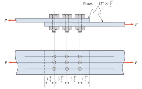
The allowable tensile loadfor the single shear lap joint.
Answer to Problem 19.1P
Explanation of Solution
Given:
The lap joint is single shear.
So,
The diameter of the bolt is
ASTM
Calculation:
Now, calculate the area of the bolt
That is,
The allowable load for the connection, based on bolt shear
Where, N is the number of bolts.
And, from the table of allowable stresses of steel on steel fastener (A325-X)
Now, calculate the allowable load for the connection based on bearing on connected material
Where,
That is,
Now, calculating allowable tensile load based on the gross area.
Where,
And, fom the ASTM 36
Now, calculating the allowable tensile load based on the net area.
Where,
So,
Therefore, load will be
Conclusion:
By comparing all, the tensile load for the single shear joint is
Want to see more full solutions like this?
Chapter 19 Solutions
Applied Statics and Strength of Materials (6th Edition)


- Law of Sines Solve the following problems using the Law of Sin 7. Find side x. All dimensions are in inches. -°-67°-37° 81° x Sin A 8.820 X 67°00' 32°00' a sin A b C sin B sin Carrow_forward35. a. Determine B. b. Determine side b. c. Determine side c. 5.330 in.- ZB 73°30'arrow_forwardConsider a 12 cm internal diameter, 14 m long circular duct whose interior surface is wet. The duct is to be dried by forcing dry air at 1 atm and 15 degrees C throught it at an average velocity of 3m/s. The duct passes through a chilled roo, and it remains at an average temp of 15 degrees C at all time. Determine the mass transfer coeeficient in the duct.arrow_forward
- 1. Calculation Calculate the DOF of the following mechanis m 2 3 1 Please enter the answerarrow_forwarda) Determine state of stress at all points (a, b and c). These points are located on the exteriorsurface of the beam. Point a is located along the centreline of the beam, point b is 15mmfrom the centreline and point c is located on the edge of the beam. Present yourresults in a table and ensure that your sign convention is clearly shownb) Construct Mohrs circle at this point andcalculate the principal stresses and maximum in‐plane shear stress (τmax) at pointc. sketch the resulting state of stress at this point clearly indicating themagnitude of the stresses and any angles associated with the state of stress (principal ormaximum in‐plane shear).arrow_forwardparts e,f,garrow_forward
 Elements Of ElectromagneticsMechanical EngineeringISBN:9780190698614Author:Sadiku, Matthew N. O.Publisher:Oxford University Press
 Mechanics of Materials (10th Edition)Mechanical EngineeringISBN:9780134319650Author:Russell C. HibbelerPublisher:PEARSON
 Thermodynamics: An Engineering ApproachMechanical EngineeringISBN:9781259822674Author:Yunus A. Cengel Dr., Michael A. BolesPublisher:McGraw-Hill Education
 Control Systems EngineeringMechanical EngineeringISBN:9781118170519Author:Norman S. NisePublisher:WILEY
 Mechanics of Materials (MindTap Course List)Mechanical EngineeringISBN:9781337093347Author:Barry J. Goodno, James M. GerePublisher:Cengage Learning
 Engineering Mechanics: StaticsMechanical EngineeringISBN:9781118807330Author:James L. Meriam, L. G. Kraige, J. N. BoltonPublisher:WILEY