
Concept explainers
Videos
Draw a control circuit with no-voltage protection. Describe how this method of wiring protects the machine operator.
Draw a control circuit with no-voltage protection and describe how this method of wiring protects the machine operator.
Explanation of Solution
The three wire control circuit uses start-stop stations, momentary contact, and holding circuit interlock connected in a parallel form with the start pushbutton in order to maintain the circuit. The no-voltage protection can be obtained using the three wire control circuit. The control circuit with no-voltage protection is drawn as Figure 1.
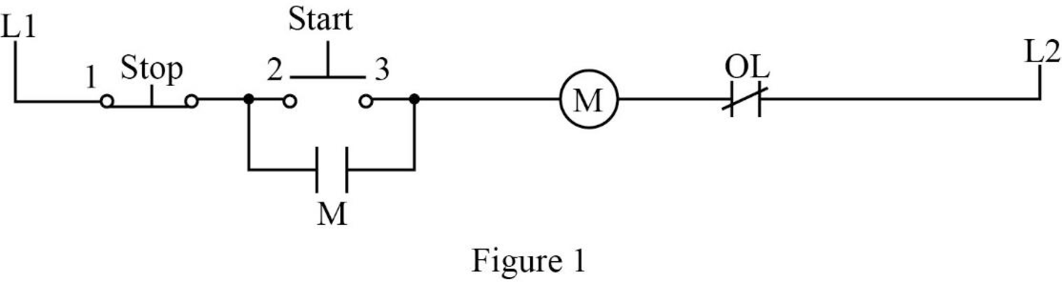
In Figure 1, when the start pushbutton is pressed, the control circuit can be completed using coil M and closes all the M contacts. It leads to close the motor connection to the line by contacting the power circuits to the motor. The auxiliary contact M, which is connected in parallel with the start pushbutton, is also closed. This M contact is used to maintain the circuit to coil M when the start pushbutton is released. Such a contact is called as holding or sealing or maintaining contact.
When the stop pushbutton is pressed, the circuit brakes and opens the contact M. After releasing the stop pushbutton, the circuit remains the same because the start pushbutton and holding contact is in the open state. In order to complete the circuit, the start pushbutton should be pressed again.
If the supply voltage of the circuit fails, it could lead to de-energize the circuit. When the power or supply voltage is restored, the circuit remains in the open state until the start pushbutton is pressed manually. Therefore, this arrangement is called as no-voltage protection and such an arrangement is used to protect both the operator and the equipment.
Conclusion:
Thus, the control circuit with no-voltage protection is drawn and the working process is explained.
Want to see more full solutions like this?
Chapter 18 Solutions
Electric Motor Control


- Medium 1 is a lossless dielectric (ε₁=ε,ε, μ₁=μ₁, σ₁=0) Medium 2 is a lossless dielectric (ε=&&₂, μ=μ₁, σ₁=0) [бг Мо о = = 0] [2 Mo σ₂ = 0] E₁ (z) = Ele² + Пe+jB₁²] E2 (z) = E Te² and tot = constant 1. For the case εr1 = 1, &r2= 16, E₁x=1 V/m and a frequency f = 750 MHz determine: λι = n₁ = 22 = n2= r = T= 2. The magnitude |E1 tot (z)| will show an interference pattern in region 1 as: E˜(z)=E,{1+Te®®]e¯MS =E||{1+Te^^^^\]e=##} | = |E|+Texp(j) For an incident field E₁x=1 V/m SKETCH the magnitude of E1 tot (z)| and |E20 (z) on the graph below. Plot the values at 2/4 increments and sketch between. What is the SWR?arrow_forwardPlease don't use AIarrow_forwardPlease don't use AIarrow_forward
- 3) In the ideal autotransformer circuit shown below find 11, 12 and lo. Find the average power delivered to the load. (hint: write KVL for both sides) 20/30° V(+ 2-1602 200 turns V₂ 10 + j40 Ω 80 turns V₁arrow_forward11-2) Now consider that white noise (i.e., noise with a PSD that is constant with frequency) is introduced in the channel of the system described in the previous problem. An ideal low pass filter is used at the receiver input to reduce the noise as much as possible, while transmitting the desired signal. (a) By what factor should the cutoff frequency of the noise reduction filter be reduced in the 16-PAM case, compared to binary? (b) By what factor will the noise power at the decision circuit be reduced in the 16-PAM case? (c) By what factor will the noise amplitude at the decision circuit be reduced in the 16-PAM case? (d) To obtain the same symbol error rate for 16-PAM as for binary, how should the minimum level spacing for 16-PAM compare to binary? (e) If the 16-PAM level spacing is adjusted according to part (d) above, by what factor will the average signal power be increased in the 16-PAM case, compared to binary?arrow_forward11-1) similar to Lathi & Ding, Prob. P.6.7-5 Data at a bit rate Rb must be transmitted using either binary NRZ polar signaling or 16-ary PAM NRZ polar signaling. (a) By what factor will the symbol rate be reduced in the 16-PAM case? (b) By what factor will bandwidth required from the (lowpass) channel be reduced in the 16-PAM case? (c) Assuming the minimum spacing between pulse levels must be the same in both cases, by what factor will the average power be increased in the 16-PAM case? [Hint: take the pulse amplitudes to be ±A in the binary case, and ±A, ±3A, ±5A,..., ±154, and recall that scaling pulse amplitude by a factor k scales the pulse energy by a factor R². Assume that the data is random, so that all 16 levels are equally likely, and that the same pulse shape is used in both cases.] Warning: Solutions to the textbook problem that are posted online are mostly wrong. Work it out for yourself.arrow_forward
- 11-3) similar to Lathi & Ding, Prob. P.6.8-1 Consider the carrier modulator shown in the figure below, which transmits a binary carrier signal. The baseband generator uses polar NRZ signaling with rectangular pulses. The data rate is 8 Mbit/s. (a) If the modulator generates a binary PSK signal, what is the bandwidth of the modulated output? (b) If the modulator generates FSK with the difference fel - fco = 6 MHz (cf. Fig 6.32c), determine the modulated signal bandwidth. Binary data source Baseband signal generator Modulated output Modulator N-E---arrow_forwardFor the circuit shown, find (i) closed-loop voltage gain (ii) Z i of the circuit (iii) f_max. The slew rate is 0.6V/us. ((write your answer in Kilo ohm)) 2Vpp R ww 20 kQ R₁ ww 200 ΚΩ 9+18 V - 18 V 10 kn R₁₂ ΚΩ ((write your answer in KHz))arrow_forwardillustrate the phenomenon of phase reversal in CE amplifier i- When signal current =OA, so IB-8uA ii- When input signal reaches positive peak, so IB=16uA ii- When input signal reaches negative peak, so IB=4uA R₁ www + Vcc = 12V Rc=6kn 16 A 8 μA 4 μА 0 www RE ẞ = 100 VCarrow_forward
- In the circuit shown, find the voltage gain. Given that ẞ = 80 and input resistance Rin=2kQ. SIGNAL +10 V Rc=6kn 4-2 210arrow_forwardFor the transistor amplifier shown, R₁-11kQ, R2=6kQ, Rc=2kQ, RE-3kQ and R₁=2k0. (i) Draw d.c. load line (ii) Determine the DC operating point (iii) Draw a.c. load line. Assume V_BE = 0.7 V. and determine the new operating point + Vcc = 15 V RC Cc Cin R1 wwwwww wwwww R₁₂ RE CE RLarrow_forwardthe first part is the second part write your answer such as: (AND, OR, INVERTER, NAND, NOR) D₁ AK D, R₁ B K First Part? the third part is , and the total are R4 R7 Output R5 R₁ T R6 R3 -UBB Second Part? Third Part? Total?arrow_forward

 Delmar's Standard Textbook Of ElectricityElectrical EngineeringISBN:9781337900348Author:Stephen L. HermanPublisher:Cengage Learning
 Electricity for Refrigeration, Heating, and Air C...Mechanical EngineeringISBN:9781337399128Author:Russell E. SmithPublisher:Cengage Learning