Electric Circuits Plus Mastering Engineering with Pearson eText 2.0 - Access Card Package (11th Edition) (What's New in Engineering)
11th Edition
ISBN: 9780134814117
Author: NILSSON, James W., Riedel, Susan
Publisher: PEARSON
bartleby

Videos

Question
Book Icon
Chapter 18, Problem 1P
To determine

Find the g and h parameters for the given circuit.

Expert Solution & Answer
Check Mark

Answer to Problem 1P

The value of g parameters g11, g12, g21, and g22 for the given circuit are 0.1S, 0.75, 0.75, and 3.75Ω respectively, and the value of h parameters h11, h12, h21, and h22 for the given circuit are 4Ω, 0.8, 0.8, and 0.1067S respectively.

Explanation of Solution

Given data:

Refer to given figure in the textbook.

Formula used:

Write the expression to find inverse hybrid or g parameters for the circuit.

g11=I1V1|I2=0        (1)

g21=V2V1|I2=0        (2)

g12=I1I2|V1=0        (3)

g22=V2I2|V1=0        (4)

Here,

g11 is the open circuit input admittance,

g12 is the short circuit reverse current gain,

g21 is the open circuit forward voltage gain, and

g22 is the short circuit output impedance.

Write the expression to find hybrid or h parameters for the circuit.

h11=V1I1|V2=0        (5)

h21=I2I1|V2=0        (6)

h12=V1V2|I1=0        (7)

h22=I2V2|I1=0        (8)

Here,

h11 is the input admittance of the network,

h12 is the reverse voltage gain,

h21 is the forward current gain, and

h22 is the output impedance of the network.

Calculation:

When port 2 is open (I2=0), we can apply a 1A current source at port 1 to find V1 and V2. The modified circuit is shown in Figure 1.

Electric Circuits Plus Mastering Engineering with Pearson eText 2.0 - Access Card Package (11th Edition) (What's New in Engineering), Chapter 18, Problem 1P , additional homework tip  1

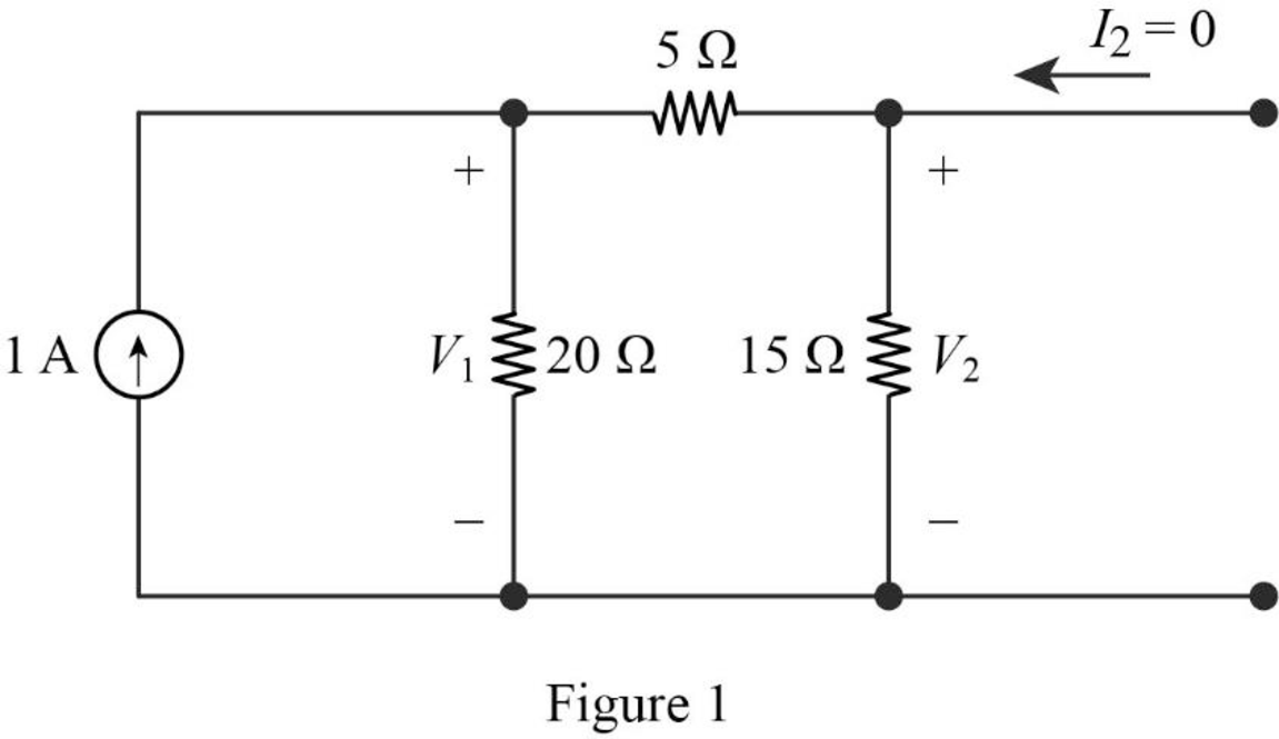
Find the equivalent impedance of the circuit in Figure 1.

Zeq=(20Ω)(5Ω+15Ω)=(20Ω)(20Ω)=20×2020+20Ω=10Ω

Write the expression to calculate voltage V1.

V1=Zeq(1A)

Substitute 10Ω for Zeq.

V1=(10Ω)(1A)=10V

Calculate the voltage V2 using voltage division rule.

V2=(1515+5)V1=1520(10V)=7.5V

Substitute 1A for I1 and 10V for V1 in equation (1) to find g11.

g11=1A10V=0.1S

Substitute 7.5V for V2 and 10V for V1 in equation (2) to find g21.

g21=7.5V10V=0.75

When port 1 is short circuited (V1=0), the reduced circuit is shown in Figure 2.

Electric Circuits Plus Mastering Engineering with Pearson eText 2.0 - Access Card Package (11th Edition) (What's New in Engineering), Chapter 18, Problem 1P , additional homework tip  2

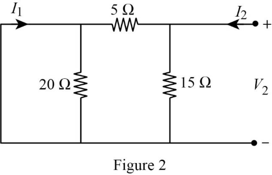
In Figure 2, the short circuit path neglects the effect of 20Ω resistor.

From Figure 2, write the expression for current I2.

I2=V215+V25=(115+15)V2=415V2

V2=154I2        (9)

Substitute equation (9) in (4) to find g22.

g22=154I2I2=3.75Ω

From Figure 2, write the expression for current I1.

I1=(1515+5)I2

I1=1520I2        (10)

Substitute equation (10) in (3) to find g12.

g12=1520I2I2=0.75

When port 1 is open (I1=0), we can apply a 1A current source at port 2 to find V1 and V2. The modified circuit is shown in Figure 3.

Electric Circuits Plus Mastering Engineering with Pearson eText 2.0 - Access Card Package (11th Edition) (What's New in Engineering), Chapter 18, Problem 1P , additional homework tip  3

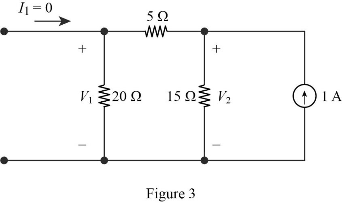
Find the equivalent impedance of the circuit in Figure 3.

Zeq=(15Ω)(5Ω+20Ω)=(15Ω)(25Ω)=15×2515+25Ω=9.375Ω

Write the expression to calculate voltage V2.

V2=Zeq(1A)

Substitute 9.375Ω for Zeq.

V2=(9.375Ω)(1A)=9.375V

Calculate the voltage V1 using voltage division rule.

V1=(2020+5)V2=2025(9.375V)=7.5V

Substitute 7.5V for V1 and 9.375V for V2 in equation (7) to find h12.

h12=7.5V9.375V=0.8

Substitute 1A for I2 and 9.375V for V2 in equation (8) to find h22.

h22=1A9.375V=0.1067S

When port 2 is short circuited (V2=0), the reduced circuit is shown in Figure 4.

Electric Circuits Plus Mastering Engineering with Pearson eText 2.0 - Access Card Package (11th Edition) (What's New in Engineering), Chapter 18, Problem 1P , additional homework tip  4

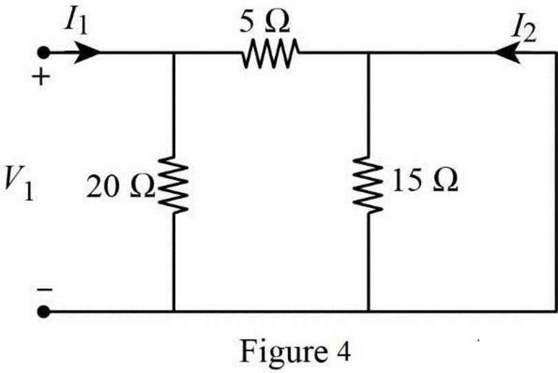
In Figure 4, the short circuit path neglects the effect of 15Ω resistor.

From Figure 1, write the expression for current I1.

I1=V120+V15=(120+15)V1=(520)V1

V1=4I1        (11)

Substitute equation (11) in (5) to find h11.

h11=4I1I1=4Ω

From Figure 4, write the expression for current I2.

I2=(2020+5)I1

I2=(2025)I1        (12)

Substitute equation (12) in (6) to find h21.

h21=(2025)I1I1=0.8

Conclusion:

Thus, the value of g parameters g11, g12, g21, and g22 for the given circuit are 0.1S, 0.75, 0.75, and 3.75Ω respectively, and the value of h parameters h11, h12, h21, and h22 for the given circuit are 4Ω, 0.8, 0.8, and 0.1067S respectively.

Want to see more full solutions like this?

Subscribe now to access step-by-step solutions to millions of textbook problems written by subject matter experts!
Students have asked these similar questions
A wattmeter is connected with the positive lead on phase “a” of a three-phase system.  The negative lead is connected to phase “b”. A separate wattmeter has the positive lead connected to phase “c”.  The negative lead of this wattmeter is connected also to phase “b”.  If the input voltage is 208 volts line-to-line, the phase sequence is “abc” and the load is 1200 ohm resistors connected in “Y”, what is the expected reading of each of the wattmeters? (Hint: draw a phasor diagram)
a b 1 ΚΩΣ 56002 82092 470Ω Rab, Rbc, Rde d e O 470Ω Σ 5 Ω 25$ 5602 3 4 Ω
MY code is experiencing a problem as I want to show both the magnitude ratio on low pass, high pass, and bandbass based on passive filters: Code: % Define frequency range for the plot f = logspace(1, 5, 500); % Frequency range from 10 Hz to 100 kHz w = 2*pi*f; % Angular frequency   % Parameters for the filters (you can modify these) R = 1e3; % Resistance in ohms (1 kOhm) C = 1e-6; % Capacitance in farads (1 uF) L = 10e-3; % Inductance in henries (10 mH)   % Transfer function for Low-pass filter: H_low = 1 / (1 + jωRC) H_low = 1 ./ (1 + 1i*w*R*C);   % Transfer function for High-pass filter: H_high = jωRC / (1 + jωRC) H_high = 1i*w*R*C ./ (1 + 1i*w*R*C);   % Transfer function for Band-pass filter: H_band = jωRC / (1 + jωL/R + jωRC) H_band = 1i*w*R*C ./ (1 + 1i*w*L/R + 1i*w*R*C);   % Plot magnitude responses figure; subplot(3,1,1); semilogx(f, 20*log10(abs(H_low))); % Low-pass filter title('Magnitude Response of Low-pass Filter'); xlabel('Frequency (Hz)'); ylabel('Magnitude (dB)'); grid…

Chapter 18 Solutions

Electric Circuits Plus Mastering Engineering with Pearson eText 2.0 - Access Card Package (11th Edition) (What's New in Engineering)

Knowledge Booster
Background pattern image
Electrical Engineering
Learn more about
Need a deep-dive on the concept behind this application? Look no further. Learn more about this topic, electrical-engineering and related others by exploring similar questions and additional content below.
Similar questions
SEE MORE QUESTIONS
Recommended textbooks for you
Text book image
Introductory Circuit Analysis (13th Edition)
Electrical Engineering
ISBN:9780133923605
Author:Robert L. Boylestad
Publisher:PEARSON
Text book image
Delmar's Standard Textbook Of Electricity
Electrical Engineering
ISBN:9781337900348
Author:Stephen L. Herman
Publisher:Cengage Learning
Text book image
Programmable Logic Controllers
Electrical Engineering
ISBN:9780073373843
Author:Frank D. Petruzella
Publisher:McGraw-Hill Education
Text book image
Fundamentals of Electric Circuits
Electrical Engineering
ISBN:9780078028229
Author:Charles K Alexander, Matthew Sadiku
Publisher:McGraw-Hill Education
Text book image
Electric Circuits. (11th Edition)
Electrical Engineering
ISBN:9780134746968
Author:James W. Nilsson, Susan Riedel
Publisher:PEARSON
Text book image
Engineering Electromagnetics
Electrical Engineering
ISBN:9780078028151
Author:Hayt, William H. (william Hart), Jr, BUCK, John A.
Publisher:Mcgraw-hill Education,
Introduction to Logic Gates; Author: Computer Science;https://www.youtube.com/watch?v=fw-N9P38mi4;License: Standard youtube license