
Videos
Find the
Answer to Problem 1P
The value of
Explanation of Solution
Given data:
Refer to given figure in the textbook.
Formula used:
Write the expression to find inverse hybrid or
Here,
Write the expression to find hybrid or
Here,
Calculation:
When port 2 is open
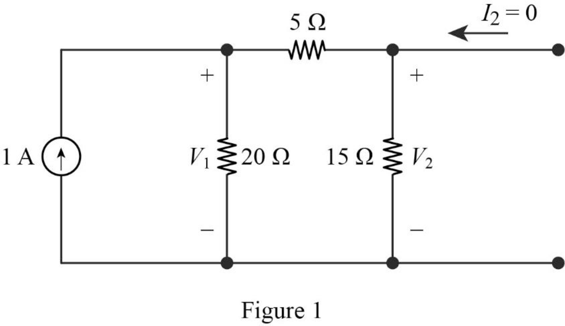
Find the equivalent impedance of the circuit in Figure 1.
Write the expression to calculate voltage
Substitute
Calculate the voltage
Substitute
Substitute
When port 1 is short circuited
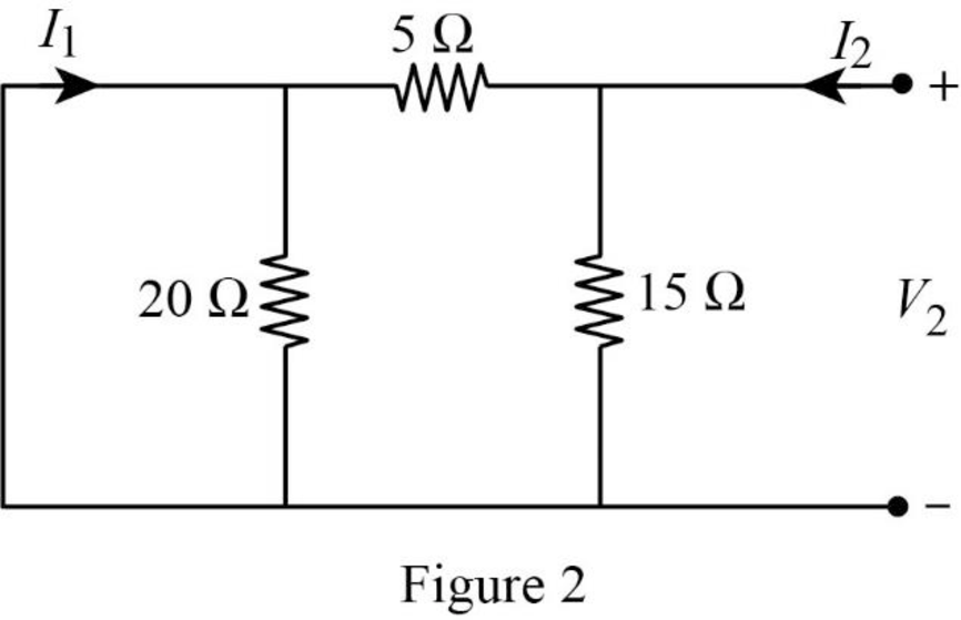
In Figure 2, the short circuit path neglects the effect of
From Figure 2, write the expression for current
Substitute equation (9) in (4) to find
From Figure 2, write the expression for current
Substitute equation (10) in (3) to find
When port 1 is open
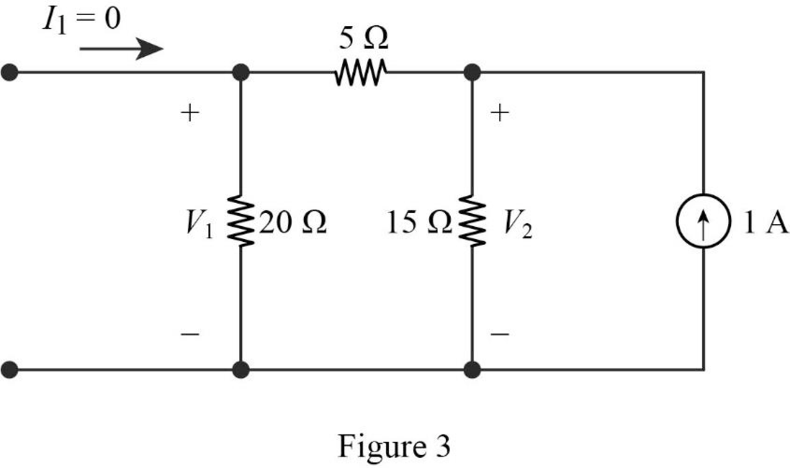
Find the equivalent impedance of the circuit in Figure 3.
Write the expression to calculate voltage
Substitute
Calculate the voltage
Substitute
Substitute
When port 2 is short circuited
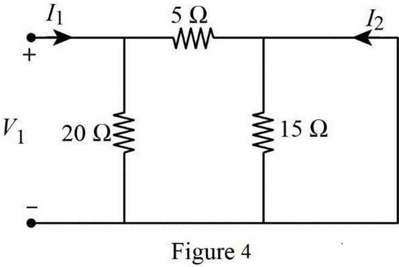
In Figure 4, the short circuit path neglects the effect of
From Figure 1, write the expression for current
Substitute equation (11) in (5) to find
From Figure 4, write the expression for current
Substitute equation (12) in (6) to find
Conclusion:
Thus, the value of
Want to see more full solutions like this?
Chapter 18 Solutions
Electric Circuits, Student Value Edition Format: Unbound (saleable)


- A single phase has two group A and B, 50 Hz, overhead line system has radius of conductor 0.5 cm. Calculate the total inductance of the line 21 A a2 b₂ 4 m B b₁ 3m 6 cm 2 marrow_forwardIn a single phase below, conductors a₁ and a₂ are in parallel form one circuit while conductors b₁ and b₂ in parallel form the return path. Calculate the total inductance of the line per km assuming that current is equally shared by the two parallel conductors. Conductor diameter in 2-0 cm. a₁ az b₁ b₂ 100 cm 20 cm 20 cmarrow_forwardDon't use ai to answer I will report you answerarrow_forward
- Don't use ai to answer I will report you answerarrow_forward4. Discussion: GINEE Compare between theoretical combination effect of Kp and KD at first order and second order systems regarding steady-state errors and transient responses with the practical obtained results whenever applying step input signalın Experiment PD controller و المهندسة الكهربائيةarrow_forwardDon't use ai to answer I will report you answerarrow_forward
- Don't use ai to answer I will report you answerarrow_forwardPlot the magnitude spectrum analytically predict by the equation below: n=∞ s(t) = Σ In (ß) cos[2π(fc +nfm)t] n=-∞ fc = 1MHz fm = 10 kHz B = 5arrow_forwardb C Is 3601116-67 Bre ✓ BIb ≤5K 20k e 0-25K 7. Zo Z Zb B=100, Ble=1Kr Zb=S & Zin = S, Zo=S, AV=Sarrow_forward
 Introductory Circuit Analysis (13th Edition)Electrical EngineeringISBN:9780133923605Author:Robert L. BoylestadPublisher:PEARSON
 Delmar's Standard Textbook Of ElectricityElectrical EngineeringISBN:9781337900348Author:Stephen L. HermanPublisher:Cengage Learning
 Programmable Logic ControllersElectrical EngineeringISBN:9780073373843Author:Frank D. PetruzellaPublisher:McGraw-Hill Education
 Fundamentals of Electric CircuitsElectrical EngineeringISBN:9780078028229Author:Charles K Alexander, Matthew SadikuPublisher:McGraw-Hill Education
 Electric Circuits. (11th Edition)Electrical EngineeringISBN:9780134746968Author:James W. Nilsson, Susan RiedelPublisher:PEARSON
 Engineering ElectromagneticsElectrical EngineeringISBN:9780078028151Author:Hayt, William H. (william Hart), Jr, BUCK, John A.Publisher:Mcgraw-hill Education,