
Videos
Create a written algorithm and flowchart to determine if a material is in the solid, liquid, or gaseous state given the temperature. The algorithm should acquire the name of the material, its freezing and boiling temperatures, and the actual temperature of the material from the user.
Write an algorithm that determines the state of a material at a given temperature for user specified material, freezing point and boiling point.
Explanation of Solution
Known:
- If the temperature is below freezing point, the material is in solid state.
- If the temperature is above the boiling point, the material is in gaseous state.
Unknown:
- The type of the material.
- The freezing point of the material.
- The boiling point of the material.
Assumptions:
- Assume that the interpreter of the algorithm will input the type of material, freezing point of the material, boiling point of the material and the temperature of the material.
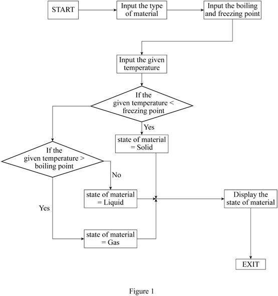
Algorithm:
- Input the type of material, the numerical value of freezing point of the material, boiling point of the material and the temperature of the material.
- Ask if the temperature of the material is less than the freezing point.
-
- a. If yes, state of the material is Solid.
- b. If no, ask if the temperature of the material is greater than the boiling point.
- 1. If yes, the state of the material is Gas.
- 2. If no, the state of the material is Liquid.
- Display the type of the material and the state of the material at the given temperature.
- End the process.
Rules for creating a proper linear flowchart are as follows.
- The flowchart contains START rectangle to mention the beginning of a process.
- All the actions must be mentioned within rectangles.
- Connection between the blocks must be mentioned with a one-directional arrow.
- The flowchart contains END rectangle to mention the end of a process.
Flowchart to determine the state of a material is given in Figure 1.
Conclusion:
Hence, the algorithm and the flowchart that determines the state of a material at a given temperature are created.
Want to see more full solutions like this?
Chapter 18 Solutions
THINKING LIKE AN ENGINEER W/ACCESS


- Q5:(? Design the duct system of the figure below by using the balanced pressure method. The velocity in the duct attached to the AHU must not exceed 5m/s. The pressure loss for each diffuser is equal to 10Pa. 100CFM 100CFM 100CFM ☑ ☑ 40m AHU -16m- 8m- -12m- 57m 250CFM 40m -14m- 26m 36m ☑ 250CFMarrow_forwardA mass of ideal gas in a closed piston-cylinder system expands from 427 °C and 16 bar following the process law, pv1.36 = Constant (p times v to the power of 1.36 equals to a constant). For the gas, initial : final pressure ratio is 4:1 and the initial gas volume is 0.14 m³. The specific heat of the gas at constant pressure, Cp = 0.987 kJ/kg-K and the specific gas constant, R = 0.267 kJ/kg.K. Determine the change in total internal energy in the gas during the expansion. Enter your numerical answer in the answer box below in KILO JOULES (not in Joules) but do not enter the units. (There is no expected number of decimal points or significant figures).arrow_forwardmy ID# 016948724. Please solve this problem step by steparrow_forward
- My ID# 016948724 please find the forces for Fx=0: fy=0: fz=0: please help me to solve this problem step by steparrow_forwardMy ID# 016948724 please solve the proble step by step find the forces fx=o: fy=0; fz=0; and find shear moment and the bending moment diagran please draw the diagram for the shear and bending momentarrow_forwardMy ID#016948724. Please help me to find the moment of inertia lx ly are a please show to solve step by stepsarrow_forward
- My ID# 016948724arrow_forwardPlease do not use any AI tools to solve this question. I need a fully manual, step-by-step solution with clear explanations, as if it were done by a human tutor. No AI-generated responses, please.arrow_forwardPlease do not use any AI tools to solve this question. I need a fully manual, step-by-step solution with clear explanations, as if it were done by a human tutor. No AI-generated responses, please.arrow_forward
 Principles of Heat Transfer (Activate Learning wi...Mechanical EngineeringISBN:9781305387102Author:Kreith, Frank; Manglik, Raj M.Publisher:Cengage Learning
 International Edition---engineering Mechanics: St...Mechanical EngineeringISBN:9781305501607Author:Andrew Pytel And Jaan KiusalaasPublisher:CENGAGE L
 Refrigeration and Air Conditioning Technology (Mi...Mechanical EngineeringISBN:9781305578296Author:John Tomczyk, Eugene Silberstein, Bill Whitman, Bill JohnsonPublisher:Cengage Learning
 Precision Machining Technology (MindTap Course Li...Mechanical EngineeringISBN:9781285444543Author:Peter J. Hoffman, Eric S. Hopewell, Brian JanesPublisher:Cengage Learning
 Automotive Technology: A Systems Approach (MindTa...Mechanical EngineeringISBN:9781133612315Author:Jack Erjavec, Rob ThompsonPublisher:Cengage Learning
 Welding: Principles and Applications (MindTap Cou...Mechanical EngineeringISBN:9781305494695Author:Larry JeffusPublisher:Cengage Learning