
ENGR.MECH.: DYNAMICS-EBOOK>I<
14th Edition
ISBN: 9781292088785
Author: HIBBELER
Publisher: INTER PEAR
expand_more
expand_more
format_list_bulleted
Concept explainers
Videos
Textbook Question
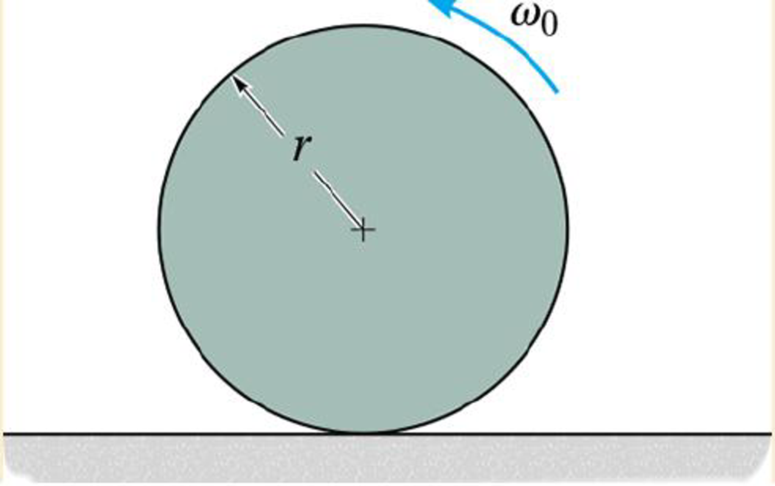
Chapter 17.5, Problem 113P
Determine the initial angular acceleration of the disk and the acceleration of its mass center. The coefficient of kinetic friction between the disk and the floor is μk.
Expert Solution & Answer
Want to see the full answer?
Check out a sample textbook solution
Students have asked these similar questions
Q5/A: A car with a track of 1.5 m and a wheelbase of 2.9 m has a steering gear
mechanism of the Ackermann type. The distance between the front stub axle pivots
is 1.3 m. The length of each track arm is 150 mm, and the length of the track rod is
1.2 m. Find the angle turned through by the outer wheel if the angle turned through
by the inner wheel is 30°.
(6 Marks)
Q5/B: Write True on the correct sentences and False on the wrong sentences
listed below:-
1- In automobiles, the power is transmitted from the gearbox to the differential
through bevel gears.
2- The minimum radius circle drawn to the cam profile is called the base circle.
3- The Proell governor, compared to the Porter governor, has less lift at the same
speed.
4- The balancing of rotating and reciprocating parts of an engine is necessary when
it runs at a slow speed.
(6.5 Marks)
***Best of Luck ***
جامعة بابل
UNIVERSITY OF BABYLON
Examiner:
Mohanad R. Hameed
Head of Department:
Dr. Dhyai H. Jawad
University of Babylon
Collage of Engineering/
Al-Musayab
Department of Automobiles
Mid Examination/ Stage: 3rd
Subject: Theory of Vehicles
Date: 14 \ 4 \2025
Time: 1.5 Hours
2025-2024
Q1: The arms of a Porter governor are 250 mm long. The upper arms are pivoted on
the axis of revolution, but the lower arms are attached to a sleeve at a distance of 50
mm from the axis of rotation. The weight on the sleeve is 600 N and the weight of
each ball is 80 N. Determine the equilibrium speed when the radius of rotation of the
balls is 150 mm. If the friction is equivalent to a load of 25 N at the sleeve, determine
the range of speed for this position.
Q2: In a loaded Proell governor shown in Figure below each ball weighs 3 kg and
the central sleeve weighs 25 kg. The arms are of 200 mm length and pivoted about
axis displaced from the central axis of rotation by 38.5 mm, y=238 mm, x=303.5
mm, CE 85 mm, MD 142.5 mm. Determine the equilibrium speed.
Fe
mg
E
M
2
Q3: In a spring loaded Hartnell type…
using the theorem of three moments, find all the reactions and supports, I need the calculations only
Chapter 17 Solutions
ENGR.MECH.: DYNAMICS-EBOOK>I<
Ch. 17.1 - The rod's density end cross-sectional area. A are...Ch. 17.1 - Determine the mass of the cylinder end its moment...Ch. 17.1 - The nag has a mass m.Ch. 17.1 - Determine the radius of gyration kx. The density...Ch. 17.1 - The specific weight of the material is = 380...Ch. 17.1 - Determine the moment of inertia Iz and express the...Ch. 17.1 - Determine the moment of inertia Ix and express the...Ch. 17.1 - Defending the moment of inertia Iy and express the...Ch. 17.1 - Express the result in terms of the mass m of the...Ch. 17.1 - Determine me radius of gyration of the pendulum...
Ch. 17.1 - Determine the mass moment of inertia of the...Ch. 17.1 - Determine the moment of inertia of the solid steel...Ch. 17.1 - Determine the wheels moment of inertia about an...Ch. 17.1 - If the large ring, small ring and each of the...Ch. 17.1 - The thin plate has a hole in its center its...Ch. 17.1 - The material has a mass per unit area of 20 kg/m2.Ch. 17.1 - The block has a mass of 3 kg and the semicylinder...Ch. 17.1 - The block has a mass of 3 kg and the semicylinder...Ch. 17.1 - The material has a specific weight = 90 lb/ft3.Ch. 17.1 - Prob. 20PCh. 17.1 - Determine the location y of the center of mass G...Ch. 17.1 - The material is steel having a density of = 7.85...Ch. 17.1 - The material is steel having a density of = 7.85...Ch. 17.3 - Draw the free-body and kinetic diagrams of the...Ch. 17.3 - Draw the free-body and kinetic diagrams of the...Ch. 17.3 - Determine the acceleration of the can and the...Ch. 17.3 - If the 80-kg cabinet is allowed to roll down the...Ch. 17.3 - Determine the maximum acceleration of the frame...Ch. 17.3 - Also what is the corresponding normal reaction on...Ch. 17.3 - Determine the tension developed in the rods and...Ch. 17.3 - If it is subjected to a couple moment M = 450 N ...Ch. 17.3 - Determine how far the door moves in 25, starting...Ch. 17.3 - Determine the constant force F that must be...Ch. 17.3 - Initially at take-off the engines provide a thrust...Ch. 17.3 - If it starts from rest it causes the rear wheels...Ch. 17.3 - If the winch at B draws in the cable with an...Ch. 17.3 - Determine the greatest acceleration of the...Ch. 17.3 - Determine the internal axial, shear, and...Ch. 17.3 - If the coefficient of kinetic friction between the...Ch. 17.3 - Determine the reactions at both the wheels at A...Ch. 17.3 - Also, what is the acceleration of the cart? The...Ch. 17.3 - If it is subjected to a horizontal force of P =...Ch. 17.3 - Determine its initial acceleration if a man pushes...Ch. 17.3 - Determine the initial acceleration of a desk when...Ch. 17.3 - Determine the maximum force P that can be applied...Ch. 17.3 - Determine the maximum force P that can be applied...Ch. 17.3 - If it is released from rest, determine the...Ch. 17.3 - It is carried on a truck as shown. Determine the...Ch. 17.3 - It is carried on a truck as shown. If the truck...Ch. 17.3 - Determine the smallest acceleration that will...Ch. 17.3 - The coefficients of static and kinetic friction...Ch. 17.3 - If the collar is given a constant acceleration of...Ch. 17.3 - If it is supported by the cable AB and hinge at C,...Ch. 17.3 - If it is supported by the cable AB and hinge at C,...Ch. 17.3 - If the acceleration is a = 20 ft/s2, determine the...Ch. 17.3 - If h = 3 ft, determine the snowmobiles maximum...Ch. 17.3 - If the carts mass is 30 kg and it is subjected to...Ch. 17.3 - The uniform rod BC has a mass of 15 kg.Ch. 17.3 - If the acceleration of the truck is at = 0.5 m/s2,...Ch. 17.3 - If the angle = 30, determine the acceleration of...Ch. 17.3 - Determine the largest initial angular acceleration...Ch. 17.3 - Determine the initial friction and normal force of...Ch. 17.3 - Determine the largest initial angular acceleration...Ch. 17.3 - Determine the normal force NE, shear force VE, and...Ch. 17.4 - If the wheel starts from rest determine its...Ch. 17.4 - Determine the angular velocity of the disk when t...Ch. 17.4 - Determine the tangential and normal components of...Ch. 17.4 - Determine the tangential and normal components or...Ch. 17.4 - Determine the horizontal and vertical components...Ch. 17.4 - If the rod has a counterclockwise angular velocity...Ch. 17.4 - If the wheel is subjected to a moment M = (5t) N ...Ch. 17.4 - Determine its initial angular acceleration and the...Ch. 17.4 - If it is released from rest when = 0. determine...Ch. 17.4 - If it is released from rest in the position shown,...Ch. 17.4 - The reel rests on rollers at A and B and has a...Ch. 17.4 - The spring has a stiffness k = 5 lb ft/rad, so...Ch. 17.4 - The spring has a stiffness k = 5 lb ft/rad, so...Ch. 17.4 - If a force of F=(142)N, where is in radians, is...Ch. 17.4 - If no slipping occurs between them determine the...Ch. 17.4 - Show that IG may be eliminated by moving the...Ch. 17.4 - Treat the beam as a uniform slender rod.Ch. 17.4 - It consists of a 100-kg steel plate AC and a...Ch. 17.4 - It is pin supported at both ends by two brackets...Ch. 17.4 - It is pin supported at both ends by two brackets...Ch. 17.4 - Determine its angular velocity when t = 2 s...Ch. 17.4 - If it is placed on the ground for which the...Ch. 17.4 - Compute the time needed to unravel 5 m of cable...Ch. 17.4 - If the rotor always maintains a constant clockwise...Ch. 17.4 - It is originally spinning at = 40 rad/s. If it is...Ch. 17.4 - It is pin supported at both ends by two brackets...Ch. 17.4 - Disk E has a weight of 60 lb and is initially at...Ch. 17.4 - If the cylinders are released from rest, determine...Ch. 17.4 - If the pulley can be treated as a disk of mass 3...Ch. 17.4 - If the pulley can be treated as a disk of mass M,...Ch. 17.4 - Assume that the board is uniform and rigid, and...Ch. 17.4 - At the instant the rolor is horizontal it has an...Ch. 17.4 - Determine the initial tending moment at the fixed...Ch. 17.4 - Movement is controlled by the electromagnet E,...Ch. 17.4 - If it is rotating in the vertical plane at a...Ch. 17.4 - Determine the angular acceleration of the rod and...Ch. 17.4 - Determine the horizontal and vertical components...Ch. 17.4 - Determine the horizontal and vertical components...Ch. 17.5 - If the powder burns at a constant rate of 20 g/s...Ch. 17.5 - Determine the acceleration of the bars mass center...Ch. 17.5 - Determine the acceleration of its mass center and...Ch. 17.5 - When the wheel is subjected to the couple moment,...Ch. 17.5 - Determine the angular acceleration of the sphere...Ch. 17.5 - If the couple moment is applied to the spool and...Ch. 17.5 - If the rod is released from rest at = 0,...Ch. 17.5 - rolls without slipping, show that when moments are...Ch. 17.5 - If it is initially at rest and is subjected to a...Ch. 17.5 - The uniform 150-lb beam is initially at rest when...Ch. 17.5 - If the coefficients of static and kinetic friction...Ch. 17.5 - If the coefficients of static and kinetic friction...Ch. 17.5 - If the coefficients of static and kinetic friction...Ch. 17.5 - Solve Prob.17-96 if the cord and force P = 50 N...Ch. 17.5 - If the coefficients of static and kinetic friction...Ch. 17.5 - If a horizontal force of F = 80 N is applied to...Ch. 17.5 - If slipping does not occur, determine the rings...Ch. 17.5 - Neglect the thickness of the ring.Ch. 17.5 - Using a collar of negligible mass, its end A is...Ch. 17.5 - If the pin is connected to a track which is giver...Ch. 17.5 - Assume the roller to be a uniform cylinder and...Ch. 17.5 - Also, find the angular acceleration of the roller....Ch. 17.5 - Determine the bars initial angular acceleration...Ch. 17.5 - Solve Prob.17-106 if the roller is removed and the...Ch. 17.5 - If the coefficient of static friction at A is s, =...Ch. 17.5 - If the truck has an acceleration of 3 m/s2...Ch. 17.5 - A cord is wrapped around the periphery of the disk...Ch. 17.5 - If the coefficient of static friction at A is s =...Ch. 17.5 - At this instant the center of gravity of the...Ch. 17.5 - Determine the initial angular acceleration of the...Ch. 17.5 - Determine the time before it starts to roll...Ch. 17.5 - If they are released from rest determine the...Ch. 17.5 - Determine the normal force which the path exerts...Ch. 17.5 - If it is originally at rest while being supported...Ch. 17.5 - If the pin support at A suddenly fails, determine...Ch. 17.5 - Determine its angular acceleration.Ch. 17.5 - If the coefficient of kinetic friction between the...Ch. 17.5 - Determine the normal reactions at each of the...Ch. 17.5 - Determine the internal axial force Ex, shear force...Ch. 17.5 - Determine the maximum acceleration it can have if...Ch. 17.5 - The roil rest against a wall for which the...Ch. 17.5 - Determine the magnitude of force F and the initial...Ch. 17.5 - Compute the reaction at the pin O just after the...Ch. 17.5 - if the coefficient of kinetic friction at the...Ch. 17.5 - The coefficient of kinetic friction is A = 0.3.
Knowledge Booster


Learn more about
Need a deep-dive on the concept behind this application? Look no further. Learn more about this topic, mechanical-engineering and related others by exploring similar questions and additional content below.Similar questions
- Q.5: (10 Marks) Select the correct answer (choose 10 only) 1. The forward whirling speed is ......... the static structure tilting speed. (a) Less than (b) Higher than (c) equal to 2. The divergence between the forward and backward whirling speeds increases as: (a) The rotating speed increase (b) the polar moment of inertia increases (c) Both (a) and (b) (d) do not change 3. Increasing the system natural frequency can be done by: (a) add masses (b) adding braces and supports (c) increase damping 4. The amplitude of vibration due to external force can be reduced by: (a) Increasing damping (b) Decreasing damping (c) Increasing mass 5. Tuned absorbers are used to: (a) Shift the natural frequency (b) increase damping (c) Increase stiffness 6. Accelerometers sensors contains: г (a) Piezoelectric materials (b) Magnet and coil (c) coil only 7. Increasing the stiffness of the system causes: (a) Less transmitted force (b) more transmitted force (c) Transmitted force does not change 8. The…arrow_forwardQ.1: (15 Marks) Find the first three natural frequencies and mode shapes of the axial and torsional vibration for a steel shaft free at both ends, having a length of 3 m. Find the subsequent axil motion if the shaft is subjected to the following initial conditions, given that E = 210 GPa, G=80 GPa, p = 7800 kg/m³: f(x)=0 v(x) = {1 2.8arrow_forwardQ.4: (15 Marks) A uniform rotor of mass 500 kg and diametral moment of inertia of 20 kg.m², is supported by identical short bearings of stiffness 1 MN/m in the horizontal and vertical directions. If the distance between the bearings is 0.6 m: (a) What is the corresponding polar moment of inertia if the backward whirling speed is 80% of the static structure tilting natural frequency? (b) Determine the forward whirling speed. 45.27arrow_forwardUniversity of Babylon Collage of Engineering/ Al-Musayab Department of Automobiles Mid Examination/ Stage: 3rd Subject: Theory of Vehicles Date: 14 \ 4 \2025 Time: 1.5 Hours 2025-2024 Q1: The arms of a Porter governor are 250 mm long. The upper arms are pivoted on the axis of revolution, but the lower arms are attached to a sleeve at a distance of 50 mm from the axis of rotation. The weight on the sleeve is 600 N and the weight of each ball is 80 N. Determine the equilibrium speed when the radius of rotation of the balls is 150 mm. If the friction is equivalent to a load of 25 N at the sleeve, determine the range of speed for this position. Q2: In a loaded Proell governor shown in Figure below each ball weighs 3 kg and the central sleeve weighs 25 kg. The arms are of 200 mm length and pivoted about axis displaced from the central axis of rotation by 38.5 mm, y=238 mm, x=303.5 mm, CE 85 mm, MD 142.5 mm. Determine the equilibrium speed. Fe mg E M 2 Q3: In a spring loaded Hartnell type…arrow_forwardQ.2: (15 Marks) = 1400 For the following system, determine the first natural frequency using Dunkerley's equation, Given that the disk has moment of inertia J = 2 kg.m², the shaft has G = 20 GPa, p kg/m³, polar moment of cross-sectional area of the shaft Ip = 8×10⁸ m². 500 mm 220 mm k=200 N/m FOF m=1 kg 14.14 56.56. W слarrow_forwardQ.2: (15 Marks) = 1400 For the following system, determine the first natural frequency using Dunkerley's equation, Given that the disk has moment of inertia J = 2 kg.m², the shaft has G = 20 GPa, p kg/m³, polar moment of cross-sectional area of the shaft Ip = 8×10⁸ m². 500 mm 220 mm k=200 N/m FOF m=1 kg 14.14 56.56. W слarrow_forwardQ1: In Figure below, pinion A having 15 teeth is fixed to motor shaft. Za-20, Z-15, where B and C are a compound gear wheel. Wheel E is keyed to the machine shaft. Arm F rotates about the same shaft on which A is fixed and carries the compound wheel B, C. If the motor runs at 1200 rpm counter-clockwise, find (a) the speed of the machine shaft and (b) ratio of the reduction gear. C B D Q1: A compound epicyclic gear is shown diagrammatically in Figure below. The gears A, D and E are free to rotate on the axis P. The compound gear B and C rotate together on the axis Q at the end of arm F. All the gears have equal pitch. The number of external teeth on the gears A, B and C are 18, 45 and 21 respectively. The gears D and E are annular gears. The gear A rotates at 100 r.p.m. in the anticlockwise direction and the gear D rotates at 450 r.p.m. clockwise. Find the speed and direction of the arm and the gear E. D E A P F LL B Carrow_forwardCalculate the force in cable AB and the angle θ for the support system shown. Round your final answers to two decimal places.arrow_forward1.53 In the steel structure shown, a 6-mm-diameter pin is used at C and 10-mm-diameter pins are used at B and D. The ultimate shearing stress is 150 MPa at all connections, and the ultimate normal stress is 400 MPa in link BD. Knowing that a factor of safety of 3.0 is desired, determine the largest load P that can be applied at A. Note that link BD is not reinforced around the pin holes. Front view D D 6 mm 18 mm B A B Side view 160 mm 120 mm A B Top viewarrow_forwardCORRECT AND DETAILED HANDWRITTEN SOLUTION WITH FBD ONLY. I WILL UPVOTE THANK YOU. CORRECT ANSWER IS ALREADY PROVIDED. 16: Determine (a) the maximum bending stress, (b)the maximum shearing stress, (c) compressive bending stress atthe roller support, and (d) the shearing stress 1 in below the topsurface of the beam at the location 1 ft to the right of the rollersupport in the simply supported beam shown in Fig. 8-70.ANS: (a) 21,945.313 lb/in2; (b) 1656.25 lb/in2; (c) 10,000 lb/in2; (d) 190.972 lb/in2arrow_forwardCORRECT AND DETAILED HANDWRITTEN SOLUTION WITH FBD ONLY. I WILL UPVOTE THANK YOU. CORRECT ANSWER IS ALREADY PROVIDED. 20: A 2022 Porsche 911 (992) GT3 is crossing a 20 ft bridge. The specification of the car is shown below.Determine the maximum shear (in lb) and moment (in lb-ft) on the bridge. ANS: Vmax = 2,680.850 lb ; Mmax = 11,233.13 lb-ftarrow_forwardCORRECT AND DETAILED HANDWRITTEN SOLUTION WITH FBD ONLY. I WILL UPVOTE THANK YOU. CORRECT ANSWER IS ALREADY PROVIDED. Answers: P1 = 208.625 KN/M P2 = 281.310 KN/M P = 15.491 KN/M FB = 463.402 MPA FV = 55.034 MPAarrow_forwardarrow_back_iosSEE MORE QUESTIONSarrow_forward_ios
Recommended textbooks for you
 Elements Of ElectromagneticsMechanical EngineeringISBN:9780190698614Author:Sadiku, Matthew N. O.Publisher:Oxford University Press
 Mechanics of Materials (10th Edition)Mechanical EngineeringISBN:9780134319650Author:Russell C. HibbelerPublisher:PEARSON
 Thermodynamics: An Engineering ApproachMechanical EngineeringISBN:9781259822674Author:Yunus A. Cengel Dr., Michael A. BolesPublisher:McGraw-Hill Education
 Control Systems EngineeringMechanical EngineeringISBN:9781118170519Author:Norman S. NisePublisher:WILEY
 Mechanics of Materials (MindTap Course List)Mechanical EngineeringISBN:9781337093347Author:Barry J. Goodno, James M. GerePublisher:Cengage Learning
 Engineering Mechanics: StaticsMechanical EngineeringISBN:9781118807330Author:James L. Meriam, L. G. Kraige, J. N. BoltonPublisher:WILEY
Elements Of Electromagnetics
Mechanical Engineering
ISBN:9780190698614
Author:Sadiku, Matthew N. O.
Publisher:Oxford University Press
Mechanics of Materials (10th Edition)
Mechanical Engineering
ISBN:9780134319650
Author:Russell C. Hibbeler
Publisher:PEARSON
Thermodynamics: An Engineering Approach
Mechanical Engineering
ISBN:9781259822674
Author:Yunus A. Cengel Dr., Michael A. Boles
Publisher:McGraw-Hill Education
Control Systems Engineering
Mechanical Engineering
ISBN:9781118170519
Author:Norman S. Nise
Publisher:WILEY
Mechanics of Materials (MindTap Course List)
Mechanical Engineering
ISBN:9781337093347
Author:Barry J. Goodno, James M. Gere
Publisher:Cengage Learning
Engineering Mechanics: Statics
Mechanical Engineering
ISBN:9781118807330
Author:James L. Meriam, L. G. Kraige, J. N. Bolton
Publisher:WILEY
Dynamics - Lesson 1: Introduction and Constant Acceleration Equations; Author: Jeff Hanson;https://www.youtube.com/watch?v=7aMiZ3b0Ieg;License: Standard YouTube License, CC-BY