
Concept explainers
Videos
In the diagram, Load A is rated at 10 amperes, 120 volts. Load B is rated at 5 amperes, 120 volts.
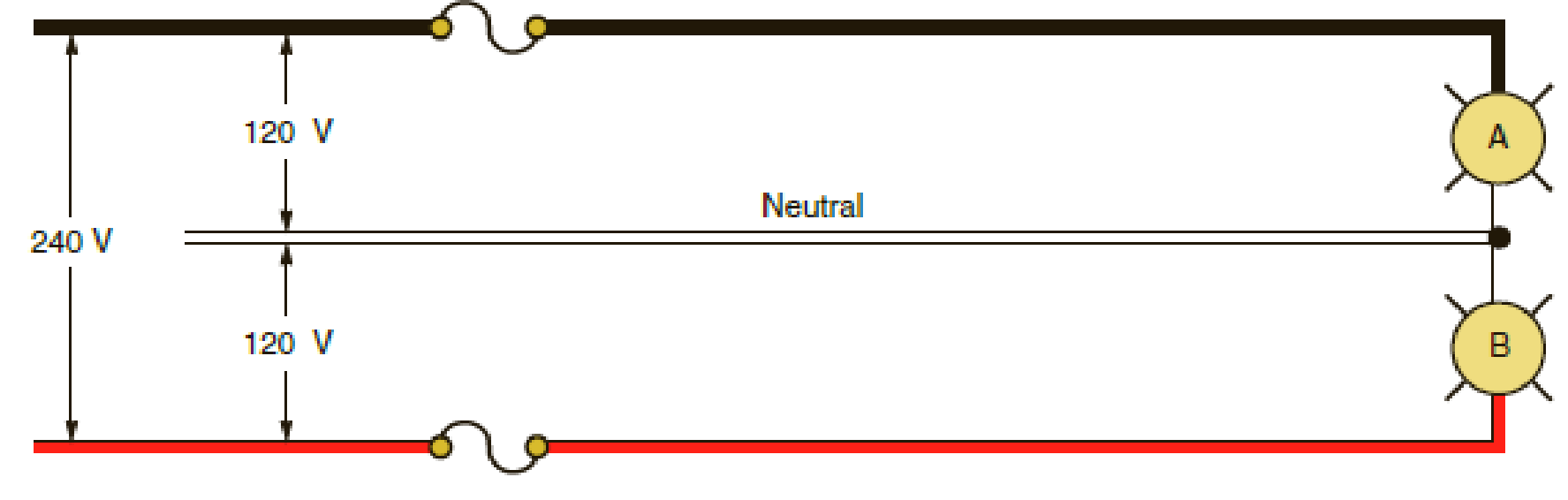
- a. When connected to the 3-wire branch circuit as indicated, how much current will flow in the neutral conductor? __________________
- b. If the neutral conductor should open, to what voltage would each load be subjected, assuming both loads were operating at the time the neutral conductor opened? Show all calculations.
a.
Find the amount of current that flows in a neutral conductor when a circuit is connected to a 3-wire branch circuit.
Answer to Problem 4R
The amount of current that flows in the neutral conductor is
Explanation of Solution
Given data:
The values of current and voltage at Load A are
The values of current and voltage at Load B are
The total voltage of the system is
Calculation:
From the given data, the values of current to Load A and Load B are not equal. Therefore, it is an unbalanced load.
For an unbalanced load, the current through the neutral conductor is calculated as follows:
Substitute
Conclusion:
Thus, the amount of current that flows in the neutral conductor is
b.
Find the voltage of each load when the neutral conductor is open.
Answer to Problem 4R
The voltage of Load A is
Explanation of Solution
Formula used:
Write an expression to calculate the resistance.
Here,
Calculation:
Substitute
Substitute
When the neutral conductor is open, Load A and Load B are connected in series. Therefore, the total resistance is calculated as follows:
Substitute
Rearrange equation (2) to find
Substitute
Rearrange equation (4) to find
For the series connected load, the current is same for both Load A and Load B.
Substitute
Substitute
Conclusion:
Thus, the voltage of Load A is
Want to see more full solutions like this?
Chapter 17 Solutions
Electrical Wiring Residential
Additional Engineering Textbook Solutions
BASIC BIOMECHANICS
Vector Mechanics For Engineers
Database Concepts (8th Edition)
Electric Circuits. (11th Edition)
Mechanics of Materials (10th Edition)
Starting Out with C++: Early Objects (9th Edition)


- A Three-phase, 12 pole, Y-connected alternator has 108 slots and 14 conductors per slot. The windings are (5/6 th) pitched. The flux per pole is 57 mWb distributed sinusoidally over the pole. If the machine runs at 500 r.p.m., determine the following: (a) The frequency of the generated e.m.f., (b) The distribution factor, (c) The pitch factor, and (d) The phase and line values of the generated e.m.f.?arrow_forwardTwo 3-ph, 6.6 kV, Y-connected, alternators supply a load of 3000 kW at 0.8 p.f. lagging. The synchronou impedance per phase of machine A is (0.5+110) and that of machine B is (0.4 +J12) . The excitation of machine A adjusted so that it delivers 150 A. The load is shared equally between the machines. Determine the armature curre p.f., induced e.m.f., and load angle of each machine?arrow_forwardName the circuit below? The output voltage is initially zero and the pulse width is 200 μs. Find the Vout and draw the output waveform? +2.5 V V 247 -2.5 V C 0.01 F Ri W 10 ΚΩarrow_forward
- Please work outarrow_forwardFind Vfinal when Vs up and Vs V. Which LED will light in each case? Red or Green? Justify your answers. Fill the table below. Vs 8 ΚΩ Vos Χρι + 3 ΚΩ www 6 ΚΩ ww 4 ΚΩ Yo www Vo Vec-12 V Nol V final Vm w 3 ΚΩ 5 V 38 ΚΩ R= 1 kQ V -12 V Red LED Green LED Vs Vo Vfinal Which LED is ON? Varrow_forwardCircuits help please solve and explain. Question in images providedarrow_forward
- + V 6.2 A 1.2 A S R 4 Ω Find the source voltage Vs 0.8 Aarrow_forwardDetermine i(t) for t≥ 0 given that the circuit below had been in steady state for a long time prior to t = 0. Also, I₁ = 1 5 A, R₁ =22, R2 =10 Q2, R3 = 32, R4 =7 2, and L=0.15 H. Also fill the table. m L ww R2 t = 0 R₁ 29 R3 R4 Time 0 iL(t) 0 8arrow_forwardPlease help explain this problemarrow_forward
- + P = 16 W w w P = 8 W I R₁ R2 E = RT=322 1- Determine R1, R2, E ΙΩarrow_forward+ 30 V = - 20 V + R 2- Use KVL to find the voltage V - V + + 8 Varrow_forwardFind the Thévenin equivalent circuit for the portions of the networks in Figure external to the elements between points a and b. a R₁ 2002 I = 0.1 A 0° Xc : 32 Ω R2 = 6802 20 Ω фъarrow_forward
 EBK ELECTRICAL WIRING RESIDENTIALElectrical EngineeringISBN:9781337516549Author:SimmonsPublisher:CENGAGE LEARNING - CONSIGNMENT