ENGR.MECH.:STAT.+DYNAMICS
15th Edition
ISBN: 9780134780955
Author: HIBBELER
Publisher: RENT PEARS
expand_more
expand_more
format_list_bulleted
Concept explainers
Videos
Textbook Question
Chapter 17, Problem 101P
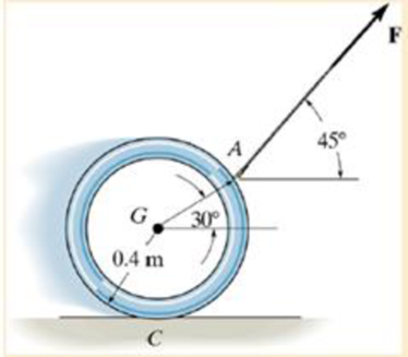
If the coefficient of static friction at C is μs = 0.3, determine the largest force F that can be applied to the 5-kg ring, without causing it to slip. Neglect the thickness of the ring.
Expert Solution & Answer
Want to see the full answer?
Check out a sample textbook solution
Students have asked these similar questions
The resistance R and load effect S for a given failure mode are statistically independent random variables
with marginal PDF's
FR (r) =
0≤r≤100
100'
fs(s)=0.05e0.05, 0
Qu 1 If crank OA rotates with an angular velocity of ω = 12 rad/s, determine the velocity of piston B and
the angular velocity of rod AB at the instant shown.
please show all work
Q2/ Maria has an online shop where she sells hand made paintings and
cards. She sells the painting for 50 and the card for 20. It takes her 2 hours
to complete 1 painting and 45 minutes to make a single card. She also has
a day job and makes paintings and cards in her free time. She cannot spend
more than 15 hours a week to make paintings and cards. Additionally, she
should make not more than 10 paintings and cards per week.
She makes a profit of 25 on painting and 15 on each card. How many
paintings and cards should she make each week to maximize her profit.
Chapter 17 Solutions
ENGR.MECH.:STAT.+DYNAMICS
Ch. 17 - Determine the moment of inertia Iy for the slender...Ch. 17 - The solid cylinder has an outer radius R1 height...Ch. 17 - Determine the moment of inertia of the thin ring...Ch. 17 - Prob. 9PCh. 17 - The pendulum consists of a 4-kg circular plate and...Ch. 17 - Prob. 12PCh. 17 - The wheel consists of a thin ring having a mass of...Ch. 17 - If the large ring, small ring and each of the...Ch. 17 - Determine the moment of inertia about an axis...Ch. 17 - Prob. 16P
Ch. 17 - Determine the location y of the center of mass G...Ch. 17 - Prob. 18PCh. 17 - Prob. 19PCh. 17 - Determine the moment of inertia of the wheel about...Ch. 17 - The pendulum consists of the 3-kg slender rod and...Ch. 17 - Prob. 22PCh. 17 - Determine the moment of inertia of the overhung...Ch. 17 - Prob. 1FPCh. 17 - Prob. 2FPCh. 17 - Prob. 3FPCh. 17 - Prob. 4FPCh. 17 - At the instant shown both rods of negligible mass...Ch. 17 - Prob. 6FPCh. 17 - The door has a weight of 200 lb and a center of...Ch. 17 - The door has a weight or 200 lb and a center of...Ch. 17 - The jet aircraft has a total mass of 22 Mg and a...Ch. 17 - The sports car has a weight of 4500 lb and center...Ch. 17 - The bar has a weight per length w and is supported...Ch. 17 - The smooth 180-lb pipe has a length of 20 ft and a...Ch. 17 - The smooth 180-lb pipe has a length of 20 ft and a...Ch. 17 - Prob. 44PCh. 17 - If the carts mass is 30 kg and it is subjected to...Ch. 17 - Prob. 50PCh. 17 - Prob. 53PCh. 17 - Prob. 54PCh. 17 - The 100-kg wheel has a radius of gyration about...Ch. 17 - Prob. 8FPCh. 17 - Prob. 9FPCh. 17 - Prob. 10FPCh. 17 - Prob. 11FPCh. 17 - Prob. 12FPCh. 17 - The 10-kg wheel has a radius of gyration kA = 200...Ch. 17 - The uniform 24-kg plate is released from rest at...Ch. 17 - The uniform slender rod has a mass m. If it is...Ch. 17 - The tent rod has a mass of 2 kg/m. If it is...Ch. 17 - Disk A has a weight of 5 lb and disk B has a...Ch. 17 - Prob. 66PCh. 17 - The reel of cable has a mass of 400 kg and a...Ch. 17 - Prob. 72PCh. 17 - Cable is unwound from a spool supported on small...Ch. 17 - The 5-kg cylinder is initially at rest when it is...Ch. 17 - Prob. 76PCh. 17 - Disk D turns with a constant clockwise angular...Ch. 17 - Prob. 78PCh. 17 - Prob. 81PCh. 17 - Prob. 85PCh. 17 - The Catherine wheel is a firework that consists of...Ch. 17 - The uniform 60-kg slender bar is initially at rest...Ch. 17 - Prob. 14FPCh. 17 - Prob. 15FPCh. 17 - The 20- kg sphere rolls down the inclined plane...Ch. 17 - The 200-kg spool has a radius of gyration about...Ch. 17 - The 12-kg slender rod is pinned to a small roller...Ch. 17 - If the disk in Fig. 17-19 rolls without slipping,...Ch. 17 - The uniform 150-lb beam is initially at rest when...Ch. 17 - The spool has a mass of 100 kg and a radius of...Ch. 17 - Solve Prob.17-96 if the cord and force P = 50 N...Ch. 17 - The spool has a mass of 100 kg and a radius of...Ch. 17 - A force of F= 10 N is applied to the 10-kg ring as...Ch. 17 - If the coefficient of static friction at C is s =...Ch. 17 - If P = 30 lb, determine the angular acceleration...Ch. 17 - If the coefficient of static friction between the...Ch. 17 - The semicircular disk having a mass of 10 leg is...Ch. 17 - The circular concrete culvert rols with an angular...Ch. 17 - The uniform disk of mass m is rotating with an...Ch. 17 - The uniform disk of mass m is rotating with an...Ch. 17 - The uniform beam has a weight W. If it is...Ch. 17 - The 500-lb beam is supported at A and B when it is...Ch. 17 - Prob. 1RPCh. 17 - Prob. 2RPCh. 17 - Prob. 3RPCh. 17 - Prob. 4RPCh. 17 - Prob. 5RPCh. 17 - Prob. 6RPCh. 17 - Prob. 7RPCh. 17 - Prob. 8RP
Knowledge Booster


Learn more about
Need a deep-dive on the concept behind this application? Look no further. Learn more about this topic, mechanical-engineering and related others by exploring similar questions and additional content below.Similar questions
- For the beam and loading shown, (a) draw the shear and bending moment diagrams, (b) determine the magnitude and location of the maximum absolute value of the bending momentConsider A = 0please show step by step process, i did something wrong with bending moment diagram( length of beam = 2 + 6 + 2)arrow_forwardCORRECT ANSWER ONLY WITH COMPLETE FBD. PREFERABLY HANDWRITTEN. I WILL UPVOTE 1. The beam shown carries the following loads:Total dead load, wDL = 36 kN/mConcentrated live load, PLL = 240 kNThe beam section is HSS16X12X3/8 with properties:Span, L = 6 mArea, A = 12,100 mm2Moment of inertia about x-axis, Ix = 292 x 106 mm4Fy = 345 MPa 1. Calculate the location of the live load, from the left support, for maximum moment to occur at the fixed support.Answer: 2.536 m2. Calculate the maximum moment. Answer: 439.128 kN-marrow_forwardCORRECT ANSWER AND COMPLETE FBD ONLY. I PREFER HANDWRITTEN BUT ITS OKAY IF NOT. I WILL UPVOTE 2. The space truss shown is supported by ball-and-socket joints at A, B and C. Factored loads P1 and P2 areacting on joints D and E, respectively, towards the negative y-direction. 1. Calculate the stress of member CE, indicate tension or compression. Answer: 23.61 MPa Tension2. Calculate the stress of member AD, indicate tension or compression. Answer: 21.01 MPa Compression3. Calculate the stress of member CD, indicate tension or compression. Answer: 11.03 MPa Tensionarrow_forward
- CORRECT ANSWER AND COMPLETE FBD ONLY. I PREFER HANDWRITTEN BUT ITS OKAY IF NOT. I WILL UPVOTE 3. The frame has pin supports at A and E, subject to a wind load. Treat joint C to be an internal hinge. Given:Dimensions, H1 = 3.0 m; H2 = 4.5 m; L = 10.0 mWind loads, wWL (AB) = 4.8 kN/m; wWL (BC) = 3.9 kN/m; wWL (CD) = 1.5 kN/m; wWL (DE) = 1.2 kN/mMembers are made of A36 steel Wide Flange Section with the following properties:Area, A = 64000 mm2Depth, d = 762 mmFlange width, bf = 371 mmThickness of web, tw = 32 mmThickness of flange, tf = 57.9 mmMoment of inertia about x-axis, Ix = 6080 x 106 mm4The wide flange is oriented so that the bending is about the x-axis1. Calculate the stress in member AB, due to the axial load it carries, indicate if tension or compression.Answer: 0.0476 MPa Tension2. Calculate the stress in member DE, due to the axial load it carries, indicate if tension or compression.Answer: 0.2351 MPa Compression3. Calculate the maximum bending stress at B. Answer: 4.282 MPaarrow_forward32 mm 32 mm b' c' C 32 mm 32 mm b PROBLEM 6.41 a The extruded beam shown has a uniform wall thickness of 3 mm. Knowing that the vertical shear in the beam is 9 kN, determine the shearing stress at each of the five points indicated.arrow_forwardIn a structural reliability problem, the resistance (capacity) R and load effect (demand) S random variables associated with a failure mode of the structure of interest are normally distributed and statistically independent with the following probability distribution parameters (or statistics) in consistent units: MR = 12, σR = 3 μs = 5, σs = 2 (a) Determine the exact probability of failure pF ·arrow_forward
- The resistance R and load effect S for a given failure mode are statistically independent random variables with marginal PDF's 1 fR (r) = 0≤r≤100 100' fs(s)=0.05e-0.05s (a) Determine the probability of failure by computing the probability content of the failure domain defined as {rarrow_forwardPlease solve this problem as soon as possible My ID# 016948724arrow_forwardThe gears shown in the figure have a diametral pitch of 2 teeth per inch and a 20° pressure angle. The pinion rotates at 1800 rev/min clockwise and transmits 200 hp through the idler pair to gear 5 on shaft c. What forces do gears 3 and 4 transmit to the idler shaft? TS I y 18T 32T This a 12 x 18T C 48T 5arrow_forwardQuestion 1. Draw 3 teeth for the following pinion and gear respectively. The teeth should be drawn near the pressure line so that the teeth from the pinion should mesh those of the gear. Drawing scale (1:1). Either a precise hand drawing or CAD drawing is acceptable. Draw all the trajectories of the involute lines and the circles. Specification: 18tooth pinion and 30tooth gear. Diameter pitch=P=6 teeth /inch. Pressure angle:20°, 1/P for addendum (a) and 1.25/P for dedendum (b). For fillet, c=b-a.arrow_forward5. The figure shows a gear train. There is no friction at the bearings except for the gear tooth forces. The material of the milled gears is steel having a Brinell hardness of 170. The input shaft speed (n2) is 800 rpm. The face width and the contact angle for all gears are 1 in and 20° respectively. In this gear set, the endurance limit (Se) is 15 kpsi and nd (design factor) is 2. (a) Find the revolution speed of gear 5. (b) Determine whether each gear satisfies the design factor of 2.0 for bending fatigue. (c) Determine whether each gear satisfies the design factor of 2.0 for surface fatigue (contact stress). (d) According to the computation results of the questions (b) and (c), explain the possible failure mechanisms for each gear. N4=28 800rpm N₁=43 N5=34 N₂=14 P(diameteral pitch)=8 for all gears Coupled to 2.5hp motorarrow_forward1. The rotating steel shaft is simply supported by bearings at points of B and C, and is driven by a spur gear at D, which has a 6-in pitch diameter. The force F from the drive gear acts at a pressure angle of 20°. The shaft transmits a torque to point A of TA =3000 lbĘ in. The shaft is machined from steel with Sy=60kpsi and Sut=80 kpsi. (1) Draw a shear force diagram and a bending moment diagram by F. According to your analysis, where is the point of interest to evaluate the safety factor among A, B, C, and D? Describe the reason. (Hint: To find F, the torque Tд is generated by the tangential force of F (i.e. Ftangential-Fcos20°) When n=2.5, K=1.8, and K₁ =1.3, determine the diameter of the shaft based on (2) static analysis using DE theory (note that fatigue stress concentration factors need to be used for this question because the loading condition is fatigue) and (3) a fatigue analysis using modified Goodman. Note) A standard diameter is not required for the questions. 10 in Darrow_forwardarrow_back_iosSEE MORE QUESTIONSarrow_forward_ios
Recommended textbooks for you
 International Edition---engineering Mechanics: St...Mechanical EngineeringISBN:9781305501607Author:Andrew Pytel And Jaan KiusalaasPublisher:CENGAGE L
International Edition---engineering Mechanics: St...
Mechanical Engineering
ISBN:9781305501607
Author:Andrew Pytel And Jaan Kiusalaas
Publisher:CENGAGE L
Column buckling; Author: Amber Book;https://www.youtube.com/watch?v=AvvaCi_Nn94;License: Standard Youtube License