
PEARSON ETEXT ENGINEERING MECH & STATS
15th Edition
ISBN: 9780137514724
Author: HIBBELER
Publisher: PEARSON
expand_more
expand_more
format_list_bulleted
Concept explainers
Videos
Textbook Question
Chapter 16, Problem 6RP
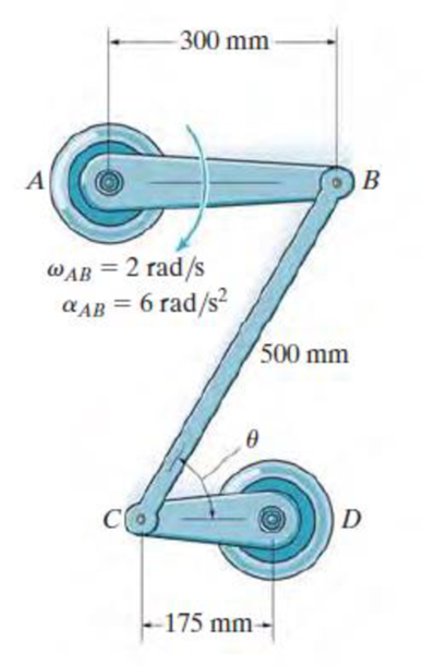
At the instant shown, link AB has an angular velocity ωAB = 2 rad/s and an angular acceleration αAB = 6 rad/s2. Determine the acceleration of the pin at C and the angular acceleration of link CB at this instant, when θ = 60°.
Expert Solution & Answer
Want to see the full answer?
Check out a sample textbook solution
Students have asked these similar questions
The resistance R and load effect S for a given failure mode are statistically independent random variables
with marginal PDF's
1
fR (r) =
0≤r≤100
100'
fs(s)=0.05e-0.05s
(a) Determine the probability of failure by computing the probability content of the failure domain defined
as {r
Please solve this problem as soon as possible My ID# 016948724
The gears shown in the figure have a diametral pitch of 2 teeth per inch and a 20° pressure angle.
The pinion rotates at 1800 rev/min clockwise and transmits 200 hp through the idler pair to gear
5 on shaft c. What forces do gears 3 and 4 transmit to the idler shaft?
TS
I
y
18T
32T
This
a
12
x
18T
C
48T
5
Chapter 16 Solutions
PEARSON ETEXT ENGINEERING MECH & STATS
Ch. 16 - When the gear rotates 20 revolutions, it achieves...Ch. 16 - The flywheel rotates with an angular velocity of ...Ch. 16 - The flywheel rotates with an angular velocity of (...Ch. 16 - The bucket is hoisted by the rope that wraps...Ch. 16 - A wheel has an angular acceleration of = (0.5 )...Ch. 16 - For a short period of time, the motor turns gear A...Ch. 16 - Prob. 1PCh. 16 - The angular acceleration of the disk is defined by...Ch. 16 - The disk is originally rotating at 0 = 12 rad/s....Ch. 16 - Prob. 4P
Ch. 16 - The disk is driven by a motor such that the...Ch. 16 - A wheel has an initial clockwise angular velocity...Ch. 16 - The disk starts from rest and is given an angular...Ch. 16 - The disk starts from rest and is given an angular...Ch. 16 - The disk starts at o = 1 rad/s when = 0, and is...Ch. 16 - A motor gives gear A an angular acceleration of A...Ch. 16 - A motor gives gear A an angular acceleration of A...Ch. 16 - Prob. 19PCh. 16 - Prob. 20PCh. 16 - If the motor turns gear A with an angular...Ch. 16 - Prob. 23PCh. 16 - Prob. 26PCh. 16 - Prob. 27PCh. 16 - Prob. 28PCh. 16 - At the instant shown, gear A is rotating with a...Ch. 16 - Determine the distance the load W is lifted in t =...Ch. 16 - Prob. 34PCh. 16 - Prob. 35PCh. 16 - Prob. 36PCh. 16 - The rod assembly is supported by ball-and-socket...Ch. 16 - Determine the velocity and acceleration of the...Ch. 16 - Prob. 54PCh. 16 - If roller A moves to the right with a constant...Ch. 16 - Prob. 8FPCh. 16 - Determine the angular velocity of the spool. The...Ch. 16 - If crank OA rotates with an angular velocity of =...Ch. 16 - Prob. 11FPCh. 16 - Prob. 12FPCh. 16 - At the instant shown the boomerang has an angular...Ch. 16 - The link AB has an angular velocity of 3 rad/s....Ch. 16 - The slider block C moves at 8 m/s down the...Ch. 16 - Determine the angular velocity of links AB and BC...Ch. 16 - The pinion gear A rolls on the fixed gear rack B...Ch. 16 - The pinion gear rolls on the gear racks. If B is...Ch. 16 - Prob. 71PCh. 16 - Prob. 72PCh. 16 - Prob. 77PCh. 16 - Prob. 13FPCh. 16 - Prob. 14FPCh. 16 - If the center O of the wheel is moving with a...Ch. 16 - If cable AB is unwound with a speed of 3 m/s, and...Ch. 16 - Prob. 17FPCh. 16 - Determine the angular velocity of links BC and CD...Ch. 16 - Prob. 81PCh. 16 - The conveyor belt is moving to the right at v = 8...Ch. 16 - The conveyor belt is moving to the right at v = 12...Ch. 16 - Prob. 92PCh. 16 - Prob. 93PCh. 16 - As the car travels forward at 80 ft/s on a wet...Ch. 16 - The crankshaft AB rotates at AB = 50 rad/s about...Ch. 16 - At the instant shown, end A of the rod has the...Ch. 16 - Prob. 20FPCh. 16 - The gear rolls on the fixed rack B. At the instant...Ch. 16 - At the instant shown, cable AB has a velocity of 3...Ch. 16 - At the instant shown, the wheel rotates with an...Ch. 16 - At the instant shown, wheel A rotates with an...Ch. 16 - At a given instant the bottom A of the ladder has...Ch. 16 - At a given instant the top B of the ladder has an...Ch. 16 - At a given instant the roller A on the bar has the...Ch. 16 - The rod is confined to move along the path due to...Ch. 16 - At a given instant the slider block A is moving to...Ch. 16 - Determine the angular acceleration of link CD if...Ch. 16 - The disk rolls without slipping such that it has...Ch. 16 - The slider block moves with a velocity of vB = 5...Ch. 16 - The slider block moves with a velocity of vB = 5...Ch. 16 - Water leaves the impeller of the centrifugal pump...Ch. 16 - Prob. 134PCh. 16 - Prob. 135PCh. 16 - Rod AB rotates counterclockwise with a constant...Ch. 16 - Prob. 137PCh. 16 - At the instant shown rod AB has an angular...Ch. 16 - Peg B on the gear slides freely along the slot in...Ch. 16 - Prob. 144PCh. 16 - A ride in an amusement park consists of a rotating...Ch. 16 - Prob. 146PCh. 16 - If the slider block C is fixed to the disk that...Ch. 16 - Prob. 1RPCh. 16 - Starting at (A)0 = 3 nad/s, when = 0, s = 0,...Ch. 16 - Prob. 3RPCh. 16 - Prob. 4RPCh. 16 - Prob. 5RPCh. 16 - At the instant shown, link AB has an angular...Ch. 16 - Prob. 7RPCh. 16 - At the given instant member AB has the angular...
Knowledge Booster


Learn more about
Need a deep-dive on the concept behind this application? Look no further. Learn more about this topic, mechanical-engineering and related others by exploring similar questions and additional content below.Similar questions
- Question 1. Draw 3 teeth for the following pinion and gear respectively. The teeth should be drawn near the pressure line so that the teeth from the pinion should mesh those of the gear. Drawing scale (1:1). Either a precise hand drawing or CAD drawing is acceptable. Draw all the trajectories of the involute lines and the circles. Specification: 18tooth pinion and 30tooth gear. Diameter pitch=P=6 teeth /inch. Pressure angle:20°, 1/P for addendum (a) and 1.25/P for dedendum (b). For fillet, c=b-a.arrow_forward5. The figure shows a gear train. There is no friction at the bearings except for the gear tooth forces. The material of the milled gears is steel having a Brinell hardness of 170. The input shaft speed (n2) is 800 rpm. The face width and the contact angle for all gears are 1 in and 20° respectively. In this gear set, the endurance limit (Se) is 15 kpsi and nd (design factor) is 2. (a) Find the revolution speed of gear 5. (b) Determine whether each gear satisfies the design factor of 2.0 for bending fatigue. (c) Determine whether each gear satisfies the design factor of 2.0 for surface fatigue (contact stress). (d) According to the computation results of the questions (b) and (c), explain the possible failure mechanisms for each gear. N4=28 800rpm N₁=43 N5=34 N₂=14 P(diameteral pitch)=8 for all gears Coupled to 2.5hp motorarrow_forward1. The rotating steel shaft is simply supported by bearings at points of B and C, and is driven by a spur gear at D, which has a 6-in pitch diameter. The force F from the drive gear acts at a pressure angle of 20°. The shaft transmits a torque to point A of TA =3000 lbĘ in. The shaft is machined from steel with Sy=60kpsi and Sut=80 kpsi. (1) Draw a shear force diagram and a bending moment diagram by F. According to your analysis, where is the point of interest to evaluate the safety factor among A, B, C, and D? Describe the reason. (Hint: To find F, the torque Tд is generated by the tangential force of F (i.e. Ftangential-Fcos20°) When n=2.5, K=1.8, and K₁ =1.3, determine the diameter of the shaft based on (2) static analysis using DE theory (note that fatigue stress concentration factors need to be used for this question because the loading condition is fatigue) and (3) a fatigue analysis using modified Goodman. Note) A standard diameter is not required for the questions. 10 in Darrow_forward
- 3 N2=28 P(diametral pitch)=8 for all gears Coupled to 25 hp motor N3=34 Full depth spur gears with pressure angle=20° N₂=2000 rpm (1) Compute the circular pitch, the center-to-center distance, and base circle radii. (2) Draw the free body diagram of gear 3 and show all the forces and the torque. (3) In mounting gears, the center-to-center distance was reduced by 0.1 inch. Calculate the new values of center-to-center distance, pressure angle, base circle radii, and pitch circle diameters. (4)What is the new tangential and radial forces for gear 3? (5) Under the new center to center distance, is the contact ratio (mc) increasing or decreasing?arrow_forward2. A flat belt drive consists of two 4-ft diameter cast-iron pulleys spaced 16 ft apart. A power of 60 hp is transmitted by a pulley whose speed is 380 rev/min. Use a service factor (Ks) pf 1.1 and a design factor 1.0. The width of the polyamide A-3 belt is 6 in. Use CD=1. Answer the following questions. (1) What is the total length of the belt according to the given geometry? (2) Find the centrifugal force (Fc) applied to the belt. (3) What is the transmitted torque through the pulley system given 60hp? (4) Using the allowable tension, find the force (F₁) on the tight side. What is the tension at the loose side (F2) and the initial tension (F.)? (5) Using the forces, estimate the developed friction coefficient (f) (6) Based on the forces and the given rotational speed, rate the pulley set. In other words, what is the horse power that can be transmitted by the pulley system? (7) To reduce the applied tension on the tight side, the friction coefficient is increased to 0.75. Find out the…arrow_forwardThe tooth numbers for the gear train illustrated are N₂ = 24, N3 = 18, №4 = 30, №6 = 36, and N₁ = 54. Gear 7 is fixed. If shaft b is turned through 5 revolutions, how many turns will shaft a make? a 5 [6] barrow_forward
- Please do not use any AI tools to solve this question. I need a fully manual, step-by-step solution with clear explanations, as if it were done by a human tutor. No AI-generated responses, please.arrow_forwardPlease do not use any AI tools to solve this question. I need a fully manual, step-by-step solution with clear explanations, as if it were done by a human tutor. No AI-generated responses, please.arrow_forwardCE-112 please solve this problem step by step and give me the correct answerarrow_forward
arrow_back_ios
SEE MORE QUESTIONS
arrow_forward_ios
Recommended textbooks for you
 International Edition---engineering Mechanics: St...Mechanical EngineeringISBN:9781305501607Author:Andrew Pytel And Jaan KiusalaasPublisher:CENGAGE L
 Principles of Heat Transfer (Activate Learning wi...Mechanical EngineeringISBN:9781305387102Author:Kreith, Frank; Manglik, Raj M.Publisher:Cengage Learning
 Precision Machining Technology (MindTap Course Li...Mechanical EngineeringISBN:9781285444543Author:Peter J. Hoffman, Eric S. Hopewell, Brian JanesPublisher:Cengage Learning
 Automotive Technology: A Systems Approach (MindTa...Mechanical EngineeringISBN:9781133612315Author:Jack Erjavec, Rob ThompsonPublisher:Cengage Learning
 Understanding Motor ControlsMechanical EngineeringISBN:9781337798686Author:Stephen L. HermanPublisher:Delmar Cengage Learning
 Refrigeration and Air Conditioning Technology (Mi...Mechanical EngineeringISBN:9781305578296Author:John Tomczyk, Eugene Silberstein, Bill Whitman, Bill JohnsonPublisher:Cengage Learning
International Edition---engineering Mechanics: St...
Mechanical Engineering
ISBN:9781305501607
Author:Andrew Pytel And Jaan Kiusalaas
Publisher:CENGAGE L
Principles of Heat Transfer (Activate Learning wi...
Mechanical Engineering
ISBN:9781305387102
Author:Kreith, Frank; Manglik, Raj M.
Publisher:Cengage Learning
Precision Machining Technology (MindTap Course Li...
Mechanical Engineering
ISBN:9781285444543
Author:Peter J. Hoffman, Eric S. Hopewell, Brian Janes
Publisher:Cengage Learning
Automotive Technology: A Systems Approach (MindTa...
Mechanical Engineering
ISBN:9781133612315
Author:Jack Erjavec, Rob Thompson
Publisher:Cengage Learning
Understanding Motor Controls
Mechanical Engineering
ISBN:9781337798686
Author:Stephen L. Herman
Publisher:Delmar Cengage Learning
Refrigeration and Air Conditioning Technology (Mi...
Mechanical Engineering
ISBN:9781305578296
Author:John Tomczyk, Eugene Silberstein, Bill Whitman, Bill Johnson
Publisher:Cengage Learning
Dynamics - Lesson 1: Introduction and Constant Acceleration Equations; Author: Jeff Hanson;https://www.youtube.com/watch?v=7aMiZ3b0Ieg;License: Standard YouTube License, CC-BY