
Mechanics of Materials
11th Edition
ISBN: 9780137605460
Author: Russell C. Hibbeler
Publisher: Pearson Education (US)
expand_more
expand_more
format_list_bulleted
Concept explainers
Videos
Textbook Question
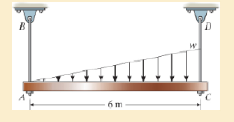
Chapter 1.5, Problem 7FP
The uniform beam is supported by two rods AB and CD that have cross-sectional areas of 10 mm2 and 15 mm2, respectively. Determine the intensity w of the distributed load so that the average normal stress in each rod does not exceed 300 kPa.
Expert Solution & Answer
Want to see the full answer?
Check out a sample textbook solution
Students have asked these similar questions
Calculate the force in cable AB and the angle θ for the support system shown. Round your final answers to two decimal places.
1.53 In the steel structure shown, a 6-mm-diameter pin is used at C and
10-mm-diameter pins are used at B and D. The ultimate shearing
stress is 150 MPa at all connections, and the ultimate normal stress
is 400 MPa in link BD. Knowing that a factor of safety of 3.0 is
desired, determine the largest load P that can be applied at A. Note
that link BD is not reinforced around the pin holes.
Front view
D
D
6 mm
18 mm
B
A
B
Side view
160 mm
120 mm
A
B
Top view
CORRECT AND DETAILED HANDWRITTEN SOLUTION WITH FBD ONLY. I WILL UPVOTE THANK YOU. CORRECT ANSWER IS ALREADY PROVIDED.
16: Determine (a) the maximum bending stress, (b)the maximum shearing stress, (c) compressive bending stress atthe roller support, and (d) the shearing stress 1 in below the topsurface of the beam at the location 1 ft to the right of the rollersupport in the simply supported beam shown in Fig. 8-70.ANS: (a) 21,945.313 lb/in2; (b) 1656.25 lb/in2; (c) 10,000 lb/in2; (d) 190.972 lb/in2
Chapter 1 Solutions
Mechanics of Materials
Ch. 1.2 - Determine the resultant internal normal force,...Ch. 1.2 - Determine the resultant internal normal force,...Ch. 1.2 - Determine the resultant internal normal force,...Ch. 1.2 - Determine the resultant internal normal force,...Ch. 1.2 - Determine the resultant internal normal force,...Ch. 1.2 - Determine the resultant internal normal force,...Ch. 1.2 - The shaft is supported by a smooth thrust bearing...Ch. 1.2 - Determine the resultant internal normal and shear...Ch. 1.2 - Determine the resultant internal torque acting on...Ch. 1.2 - Determine the resultant internal loadings in the...
Ch. 1.2 - The shaft is supported by a smooth thrust bearing...Ch. 1.2 - Determine the resultant internal loading on the...Ch. 1.2 - Determine the resultant internal loading on the...Ch. 1.2 - The 800-lb load is being hoisted at a constant...Ch. 1.2 - Determine resultant internal loadings acting on...Ch. 1.2 - Determine the resultant internal normal force...Ch. 1.2 - Determine the resultant internal loadings on the...Ch. 1.2 - Determine the resultant internal loadings on the...Ch. 1.2 - The blade of the hacksaw is subjected to a...Ch. 1.2 - The blade of the hacksaw is subjected to a...Ch. 1.2 - Determine the resultant internal loadings on the...Ch. 1.2 - Determine the resultant internal loadings on the...Ch. 1.2 - The sky hook is used to support the cable of a...Ch. 1.2 - Determine the resultant internal torque acting on...Ch. 1.2 - Determine the resultant internal loadings acting...Ch. 1.2 - Determine the resultant internal loadings on the...Ch. 1.2 - Determine the resultant internal loadings on the...Ch. 1.2 - The metal stud punch is subjected to a force of...Ch. 1.2 - The metal stud punch is subjected to a force of...Ch. 1.2 - Determine the resultant internal loadings acting...Ch. 1.2 - A force of 80 N is supported by the bracket....Ch. 1.2 - The curved rod has a radius r and is fixed to the...Ch. 1.2 - The pipe assembly is subjected to a force of 600 N...Ch. 1.2 - If the drill bit jams when the handle of the hand...Ch. 1.2 - The curved rod AD of radius r has a weight per...Ch. 1.2 - A differential element taken from a curved bar is...Ch. 1.5 - The uniform beam is supported by two rods AB and...Ch. 1.5 - Determine the average normal stress on the cross...Ch. 1.5 - Determine the average normal stress on the cross...Ch. 1.5 - If the 600-kN force acts through the centroid of...Ch. 1.5 - Determine the average normal stress at points A,...Ch. 1.5 - Determine the average normal stress in rod AB if...Ch. 1.5 - A 175-lb woman stands on a vinyl floor wearing...Ch. 1.5 - Determine the largest intensity w of the uniform...Ch. 1.5 - The specimen failed in a tension test at an angle...Ch. 1.5 - The built-up shaft consists of a pipe AB and solid...Ch. 1.5 - If the material fails when the average normal...Ch. 1.5 - If the block is subjected to a centrally applied...Ch. 1.5 - The plate has a width of 0.5 m. If the stress...Ch. 1.5 - The member is subjected to a tensile force of 200...Ch. 1.5 - The boom has a uniform weight of 600 lb and is...Ch. 1.5 - Determine the average normal stress in each of the...Ch. 1.5 - If the average normal stress in each of the...Ch. 1.5 - Determine the maximum average shear stress in pin...Ch. 1.5 - The 150-kg bucket is suspended from end E of the...Ch. 1.5 - The 150-kg bucket is suspended from end E of the...Ch. 1.5 - If the pedestal is subjected to a compressive...Ch. 1.5 - The beam is supported by two rods AB and CD that...Ch. 1.5 - The beam is supported by two rods AB and CD that...Ch. 1.5 - The beam is supported by a pin at B and a short...Ch. 1.5 - The railcar docklight is supported by the...Ch. 1.5 - The plastic block is subjected to an axial...Ch. 1.5 - During a tension test, the wooden specimen is...Ch. 1.5 - The bar has a cross-sectional area of 400(106) m2....Ch. 1.5 - The bar has a cross-sectional area of 400(106) m2....Ch. 1.5 - Prob. 54PCh. 1.5 - The 2-Mg concrete pipe has a center of mass at...Ch. 1.5 - The 2-Mg concrete pipe has a center of mass at...Ch. 1.5 - The pier is made of material having a specific...Ch. 1.5 - Prob. 58PCh. 1.5 - The uniform bar, having a cross-sectional area of...Ch. 1.5 - Prob. 60PCh. 1.5 - Prob. 61PCh. 1.5 - The triangular blocks are glued along each side of...Ch. 1.5 - The triangular blocks are glued along each side of...Ch. 1.5 - Prob. 64PCh. 1.5 - Determine the maximum magnitude P of the load the...Ch. 1.5 - Prob. 66PCh. 1.5 - Prob. 67PCh. 1.7 - Rods AC and BC are used to suspend the 200-kg...Ch. 1.7 - If it is subjected to double shear, determine the...Ch. 1.7 - Determine the maximum average shear stress...Ch. 1.7 - If each of the three nails has a diameter of 4 mm...Ch. 1.7 - The strut is glued to the horizontal member at...Ch. 1.7 - Determine the maximum average shear stress...Ch. 1.7 - If the eyebolt is made of a material having a...Ch. 1.7 - If the bar assembly is made of a material having a...Ch. 1.7 - Determine the maximum force P that can be applied...Ch. 1.7 - The pin is made of a material having a failure...Ch. 1.7 - If the bolt head and the supporting bracket are...Ch. 1.7 - Six nails are used to hold the hanger at A against...Ch. 1.7 - If A and B are both made of wood and are 38 in....Ch. 1.7 - Prob. 70PCh. 1.7 - The connection is made using a bolt and nut and...Ch. 1.7 - Determine the required cross-sectional area of...Ch. 1.7 - Prob. 73PCh. 1.7 - The spring mechanism is used as a shock absorber...Ch. 1.7 - Prob. 75PCh. 1.7 - The hangers support the joist in such a way that...Ch. 1.7 - Prob. 77PCh. 1.7 - Prob. 78PCh. 1.7 - The two aluminum rods AB and BC have diameters of...Ch. 1.7 - The cotter is used to hold the two rods together....Ch. 1.7 - Prob. 81PCh. 1.7 - The 60mm60mm oak post is supported on the pine...Ch. 1.7 - Prob. 83PCh. 1.7 - Prob. 84PCh. 1.7 - The assembly consists of three disks A, B, and C...Ch. 1.7 - Prob. 86PCh. 1.7 - Prob. 87PCh. 1.7 - Prob. 88PCh. 1.7 - Prob. 89PCh. 1.7 - Prob. 90PCh. 1.7 - Prob. 91PCh. 1.7 - Prob. 92PCh. 1.7 - Prob. 93PCh. 1.7 - The aluminum bracket A is used to support the...Ch. 1.7 - If the allowable tensile stress for the bar is...Ch. 1.7 - The bar is connected to the support using a pin...Ch. 1 - The beam AB is pin supported at A and supported by...Ch. 1 - The long bolt passes through the 30-mm-thick...Ch. 1 - Determine the required thickness of member BC to...Ch. 1 - The circular punch B exerts a force of 2 kN on the...Ch. 1 - Determine the average punching shear stress the...Ch. 1 - The 150 mm by 150 mm block of aluminum supports a...Ch. 1 - The yoke-and-rod connection is subjected to a...Ch. 1 - The cable has a specific weight (weight/volume)...
Knowledge Booster


Learn more about
Need a deep-dive on the concept behind this application? Look no further. Learn more about this topic, mechanical-engineering and related others by exploring similar questions and additional content below.Similar questions
- CORRECT AND DETAILED HANDWRITTEN SOLUTION WITH FBD ONLY. I WILL UPVOTE THANK YOU. CORRECT ANSWER IS ALREADY PROVIDED. 20: A 2022 Porsche 911 (992) GT3 is crossing a 20 ft bridge. The specification of the car is shown below.Determine the maximum shear (in lb) and moment (in lb-ft) on the bridge. ANS: Vmax = 2,680.850 lb ; Mmax = 11,233.13 lb-ftarrow_forwardCORRECT AND DETAILED HANDWRITTEN SOLUTION WITH FBD ONLY. I WILL UPVOTE THANK YOU. CORRECT ANSWER IS ALREADY PROVIDED. Answers: P1 = 208.625 KN/M P2 = 281.310 KN/M P = 15.491 KN/M FB = 463.402 MPA FV = 55.034 MPAarrow_forwardCORRECT AND DETAILED HANDWRITTEN SOLUTION WITH FBD ONLY. I WILL UPVOTE THANK YOU. CORRECT ANSWER IS ALREADY PROVIDED. 18: Determine the maximum shear and moment that would be experienced by a 10 m beam if a three-wheelmoving load of 10 kN, 30 kN, and 5 kN respectively will pass it by. The distance between the 1st and 2nd load is 1 m and the distance between the 2nd and 3rd load is 3 m.ANS: Vmax = 40 kN ; Mmax = 100.014 kN-marrow_forward
- CORRECT AND DETAILED HANDWRITTEN SOLUTION WITH FBD ONLY. I WILL UPVOTE THANK YOU. CORRECT ANSWER IS ALREADY PROVIDED. 5: A 12-m simply supported bridge is constructed with 100-mm concrete slab deck supported by precastconcrete stringers spaced 800 mm on center. Analyze the stringers when subjected to a moving load consisting of 3 evenly spaced axle loads at 3 m and equivalent to 20 kN, 30 kN and 40 kN respectively. The self-weight of the stringers is 8.5 kN/m and the concrete deck has a unit weight of 24 kN/m3 . Neglect all other superimposed loads. Calculate: (a) the maximum shear force in the stringers; (b) the maximum bending moment in the stringers. Answer: Vmax = 135.020 KN, Mmax = 477.388 KN-Marrow_forwardCORRECT AND DETAILED HANDWRITTEN SOLUTION WITH FBD ONLY. I WILL UPVOTE THANK YOU. CORRECT ANSWER IS ALREADY PROVIDED. 19: A 22-wheeler truck is crossing over 25 m bridge. The dimensions between the axles of the truck are shownin the figure below. Axles 1 to 3 carry a 90 kN load each, axles 4 and 5 carry a 65 kN load each, and the axle directly below the cab of the truck has a load of 100 kN. Determine the maximum shear and moment on the bridge.ANS: Vmax = 374.92 kN ; Mmax = 1,702.229 kN-marrow_forwardCORRECT AND DETAILED HANDWRITTEN SOLUTION WITH FBD ONLY. I WILL UPVOTE THANK YOU. CORRECT ANSWER IS ALREADY PROVIDED. 1. A H = 6 m cantilever retaining wall is subjected to a soil pressurelinearly varying from zero at the top to 90 kPa at the bottom. As an additionalsupport, it is anchored at depth y = 2 m. with maximum tension equal to 25kN. Assume that the stem provides fully retrained support. Draw the shearand moment diagram of the wall to calculate the following: (a) Maximumpositive bending moment per linear meter; (b) maximum negative bendingmoment per linear meter; (c) maximum shear force per linear meter. answer: +MMax = 440 kn-m, -Mmax = 0kn-M, Vmax = 245 KNarrow_forward
- CORRECT AND DETAILED HANDWRITTEN SOLUTION WITH FBD ONLY. I WILL UPVOTE THANK YOU. CORRECT ANSWER IS ALREADY PROVIDED. 17: A simply supported beam with the section shown below has an allowableflexural shearing stress of 43 MPa. (a) Determine the maximum allowable shearing force onthe section. And (b) what is the minimum thickness of plate that should be welded at theflanges if the section is to withstand a total shearing force of 200 kN. The additional plate willhave its base dimension equal to the flange dimension.ANS: V = 179.333 kN ; t = 23.181 mmarrow_forwardCORRECT AND DETAILED HANDWRITTEN SOLUTION WITH FBD ONLY. I WILL UPVOTE THANK YOU. CORRECT ANSWER IS ALREADY PROVIDED. Answer: A = 0.207 L(M)arrow_forwardQu 4 The 12-kg slender rod is attached to a spring, which has an unstretched length of 2 m. If the rod is released from rest when 0 = 30°, determine its angular velocity at the instant 0 = 90°. 2 m B k = 40 N/m 2 marrow_forward
- CORRECT AND DETAILED HANDWRITTEN SOLUTION WITH FBD ONLY. I WILL UPVOTE THANK YOU. CORRECT ANSWER IS ALREADY PROVIDED. 13: A cantilever beam is of length 1.5 m,loaded by a concentrated load P at its tip as shown inFig. 8-18(a), and is of circular cross section (R = 100 mm),having two symmetrically placed longitudinal holes asindicated. The material is titanium alloy, having anallowable working stress in bending of 600 MPa.Determine the maximum allowable value of the verticalforce P. ANS: P = 236,589.076 N = 236.589 kNarrow_forwardCORRECT AND DETAILED HANDWRITTEN SOLUTION WITH FBD ONLY. I WILL UPVOTE THANK YOU. CORRECT ANSWER IS ALREADY PROVIDED. 15: Consider a beam having an I-type cross section as shown in Fig. 8-45. Ashearing force V of 150 kN acts over the section. Determine the maximum and minimumvalues of the shearing stress in the vertical web of the section.ANS: fv(max) = 44.048 MPa ; fv(min) = 33.202 MPaarrow_forwardCORRECT AND DETAILED HANDWRITTEN SOLUTION WITH FBD ONLY. I WILL UPVOTE THANK YOU. CORRECT ANSWER IS ALREADY PROVIDED. 12: A steel cantilever beam 16 ft 8 in in length is subjected to a concentrated load of 320 lb acting at the freeend of the bar. A commercially available rolled steel section, designated as W12x32, is used for the beam. Assume that the total depth of the beam is 12 in, and the neutral axis of the section is in the middle. Determine the maximum tensile and compressive stresses. (Properties of commercially available rolled steel section provided in the table. Z = section modulus). ANS: σT = σC = 1,572.482 lb/in2arrow_forward
arrow_back_ios
SEE MORE QUESTIONS
arrow_forward_ios
Recommended textbooks for you
 Elements Of ElectromagneticsMechanical EngineeringISBN:9780190698614Author:Sadiku, Matthew N. O.Publisher:Oxford University Press
 Mechanics of Materials (10th Edition)Mechanical EngineeringISBN:9780134319650Author:Russell C. HibbelerPublisher:PEARSON
 Thermodynamics: An Engineering ApproachMechanical EngineeringISBN:9781259822674Author:Yunus A. Cengel Dr., Michael A. BolesPublisher:McGraw-Hill Education
 Control Systems EngineeringMechanical EngineeringISBN:9781118170519Author:Norman S. NisePublisher:WILEY
 Mechanics of Materials (MindTap Course List)Mechanical EngineeringISBN:9781337093347Author:Barry J. Goodno, James M. GerePublisher:Cengage Learning
 Engineering Mechanics: StaticsMechanical EngineeringISBN:9781118807330Author:James L. Meriam, L. G. Kraige, J. N. BoltonPublisher:WILEY
Elements Of Electromagnetics
Mechanical Engineering
ISBN:9780190698614
Author:Sadiku, Matthew N. O.
Publisher:Oxford University Press
Mechanics of Materials (10th Edition)
Mechanical Engineering
ISBN:9780134319650
Author:Russell C. Hibbeler
Publisher:PEARSON
Thermodynamics: An Engineering Approach
Mechanical Engineering
ISBN:9781259822674
Author:Yunus A. Cengel Dr., Michael A. Boles
Publisher:McGraw-Hill Education
Control Systems Engineering
Mechanical Engineering
ISBN:9781118170519
Author:Norman S. Nise
Publisher:WILEY
Mechanics of Materials (MindTap Course List)
Mechanical Engineering
ISBN:9781337093347
Author:Barry J. Goodno, James M. Gere
Publisher:Cengage Learning
Engineering Mechanics: Statics
Mechanical Engineering
ISBN:9781118807330
Author:James L. Meriam, L. G. Kraige, J. N. Bolton
Publisher:WILEY
EVERYTHING on Axial Loading Normal Stress in 10 MINUTES - Mechanics of Materials; Author: Less Boring Lectures;https://www.youtube.com/watch?v=jQ-fNqZWrNg;License: Standard YouTube License, CC-BY