
Laboratory Manual for Introductory Circuit Analysis
13th Edition
ISBN: 9780133923780
Author: Robert L. Boylestad, Gabriel Kousourou
Publisher: PEARSON
expand_more
expand_more
format_list_bulleted
Concept explainers
Videos
Textbook Question
thumb_up100%
Chapter 15, Problem 20P
For the circuit of Fig. 15.97:
- Find the current
- Find the voltage
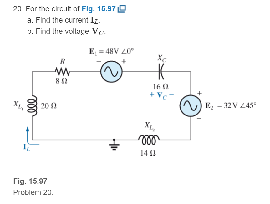
Fig. 15.97
Expert Solution & Answer
Want to see the full answer?
Check out a sample textbook solution
Students have asked these similar questions
Name the circuit below? The output voltage is initially zero and the pulse width is
200 μs. Find the Vout and draw the output waveform?
+2.5 V
V
247
-2.5 V
C
0.01 F
Ri
W
10 ΚΩ
Please work out
Find Vfinal when Vs
up
and Vs V. Which LED will light
in each case? Red or Green? Justify your answers. Fill the
table below.
Vs
8 ΚΩ
Vos
Χρι
+
3 ΚΩ
www
6 ΚΩ
ww
4 ΚΩ Yo
www
Vo
Vec-12 V
Nol
V final
Vm
w
3 ΚΩ
5 V
38 ΚΩ
R= 1 kQ
V
-12 V
Red LED
Green
LED
Vs
Vo
Vfinal
Which LED is ON?
V
Chapter 15 Solutions
Laboratory Manual for Introductory Circuit Analysis
Ch. 15 - For the resistive element in Fig. 15.81: Write the...Ch. 15 - For the resistive element in Fig. 15.82: Write the...Ch. 15 - For the inductive element of Fig. 15.83: a. Write...Ch. 15 - For the inductive element of Fig. 15.84: Calculate...Ch. 15 - For the inductive element of Fig. 15.85: Write the...Ch. 15 - For the capacitive element of Fig. 15.86: Write...Ch. 15 - For the capacitive element of Fig. 15.87:...Ch. 15 - For the capacitive element of Fig. 15.88: Write...Ch. 15 - Sketch the impedance diagram of a 120 k resistor.Ch. 15 - Sketch the impedance diagram of a 5 mH coil...
Ch. 15 - Sketch the impedance diagram of a 0.02 F capacitor...Ch. 15 - Calculate the total impedance of the circuits in...Ch. 15 - Calculate the total impedance of the circuits in...Ch. 15 - Find the type and impedance in ohms of the series...Ch. 15 - For the circuit in Fig. 15.92 Find the total...Ch. 15 - Repeat problem 15 for the circuit in Fig. 15.93,...Ch. 15 - For the circuit in Fig. 15.94: Find the total...Ch. 15 - Repeat Problem 17 for the circuit in Fig. 15.95...Ch. 15 - For the circuit of Fig. 15.96: Find the total...Ch. 15 - For the circuit of Fig. 15.97: Find the current...Ch. 15 - Prob. 21PCh. 15 - Using the oscilloscope reading in Fig. 15.99,...Ch. 15 - Using the DMM current reading and the oscilloscope...Ch. 15 - Using the oscilloscope reading in Fig. 15.101:...Ch. 15 - An electrical load has a power factor of 0.8...Ch. 15 - Find the series element or elements that must be...Ch. 15 - Calculate the voltages V1andV2 for the circuits in...Ch. 15 - Calculate the voltages V1andV2 for the circuits in...Ch. 15 - For the circuit in Fig. 15.105: Determine...Ch. 15 - For the circuit in Fig. 15.106: a. Plot ZT and T...Ch. 15 - Prob. 31PCh. 15 - For the series R-L-C circuit in Fig. 15.108: Plot...Ch. 15 - For the series R-C circuit in Fig. 15.109:...Ch. 15 - For the circuit in Fig. 15.110, determine the...Ch. 15 - For the oscilloscope traces in Fig. 15.111:...Ch. 15 - For the network in Fig. 15.92 (usef=1kHz):...Ch. 15 - For the network in Fig. 15.93: Plot the impedance...Ch. 15 - For the network in Fig. 15.105: Find the rms...
Knowledge Booster


Learn more about
Need a deep-dive on the concept behind this application? Look no further. Learn more about this topic, electrical-engineering and related others by exploring similar questions and additional content below.Similar questions
- Circuits help please solve and explain. Question in images providedarrow_forward+ V 6.2 A 1.2 A S R 4 Ω Find the source voltage Vs 0.8 Aarrow_forwardDetermine i(t) for t≥ 0 given that the circuit below had been in steady state for a long time prior to t = 0. Also, I₁ = 1 5 A, R₁ =22, R2 =10 Q2, R3 = 32, R4 =7 2, and L=0.15 H. Also fill the table. m L ww R2 t = 0 R₁ 29 R3 R4 Time 0 iL(t) 0 8arrow_forward
- Find the Thévenin equivalent circuit for the portions of the networks in Figure external to the elements between points a and b. a R₁ 2002 I = 0.1 A 0° Xc : 32 Ω R2 = 6802 20 Ω фъarrow_forwardFind the Norton equivalent circuit for the network external to the elements between a and b for the networks in Figure. E1 = 120 V Z 0° R ww 10 Ω Xc XL · 000 802 802 ① I = 0.5 AZ 60° ZL barrow_forwardUsing superposition, determine the current through inductance XL for each network in Figure I = 0.3 A 60° XL 000 802 XC 502 Ω E 10 V0° =arrow_forward
- Find the Thévenin equivalent circuit for the portions of the networks in Figure external to the elements between points a and b. E = 20 VZ0° + R ww 2 ΚΩ Хо XL 000 6ΚΩ 3 ΚΩ b RLarrow_forwardWhat percentage of the full-load current of a thermally protected continuous-duty motor of more than one Hp can the trip current be, if the full-load current is 15 amperes? Ο 122 Ο 140 156 O 170arrow_forwardQ3arrow_forward
arrow_back_ios
SEE MORE QUESTIONS
arrow_forward_ios
Recommended textbooks for you
 Power System Analysis and Design (MindTap Course ...Electrical EngineeringISBN:9781305632134Author:J. Duncan Glover, Thomas Overbye, Mulukutla S. SarmaPublisher:Cengage Learning
Power System Analysis and Design (MindTap Course ...
Electrical Engineering
ISBN:9781305632134
Author:J. Duncan Glover, Thomas Overbye, Mulukutla S. Sarma
Publisher:Cengage Learning
Nodal Analysis for Circuits Explained; Author: Engineer4Free;https://www.youtube.com/watch?v=f-sbANgw4fo;License: Standard Youtube License