
Concept explainers
Videos
a.
Design a low pass filter for a given specification.
a.
Answer to Problem 1P
The obtained value of resistor
Explanation of Solution
Given data:
The value of capacitor
The value of passband gain is
Cutoff frequency is
Formula used:
Refer to Figure 15.1 in the textbook for a first order low-pass filter.
Write the expression for passband gain.
Here,
Write the expression for cutoff frequency.
Calculation:
Write the expression for
Re-arrange equation (2) as follows.
Substitute
Substitute
Convert dB value of passband gain into normal value.
Substitute
Conclusion:
Thus, the obtained value of resistor
b.
Draw the circuit diagram of designed low pass filter.
b.
Explanation of Solution
Calculation:
Modify the Figure 15.1 for designed value as shown in Figure 1.
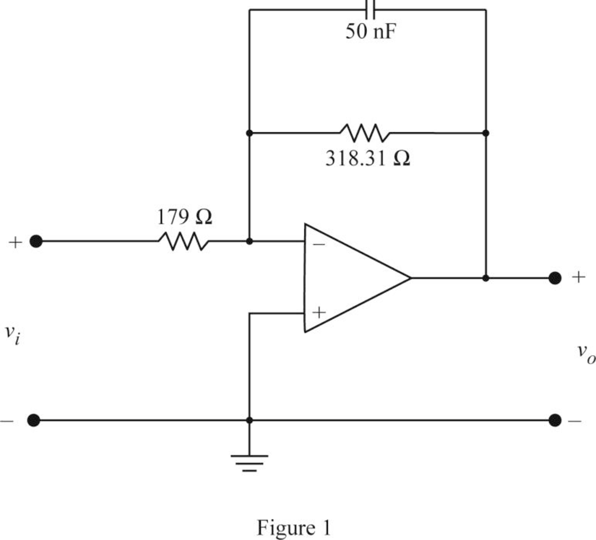
Conclusion:
Thus, the circuit diagram of designed low pass filter is shown in Figure 1.
Want to see more full solutions like this?
Chapter 15 Solutions
ELECTRIC CIRCUITS-W/MASTERINGENGINEERING


- Find the Thevenin Equivalent Circuit of the circuit below and the current through R_L , show all steps;arrow_forwardFind the Norton Equivalent of the below and the voltage across R_L, show all steps;arrow_forwardUse Mesh Analysis to find the current through the laod resistor R_L. Show all steps;arrow_forward
- Find Thevenin Equivalent of the circuit below and the current through the load resistor R_L. Show all steps;arrow_forwardIf = 5000 A actual time IDMT ---R,, Reand R3 The Tsm relays R, and R3 Draw The characteistic relays time margin between Tsm = 0.5 RCT=500/1 CS-125% TSM = 2 TSM = 0.2 and -0.6 R2 CTS = 500/1 Cs=100% Tsm=0.4 R3 CTS = 400/1 Cs=125% TSM = 2arrow_forwardLet X and Y be random variables having joint density function 01.5). (c) p(x) and p(y).arrow_forward
- The joint density function of two continuous random variables X and Y is: p(x, y) = {cxy 0 < x < 4,1 < y < 5 0 otherwise Find (i) the constant c (ii)P(1arrow_forwardBelow is a rough schematic of the lighting system for a streetcar powered by a 120 VDC supply. How can I arrange the wires inside the trolley for the interior lights (1-16), headlights (19-20), doors (21-24), and platform lights (17-18), ensuring that each has its own switch? Does the electrical system require additional safety components? What type of cable can be used for wiring these lights?arrow_forward12.8 Obtain the inverse Laplace transform of each of the fol- lowing functions by first applying the partial-fraction-expansion method. (a) Fi(s) 6 = (s+2)(s+4) (b) F2(s) = (c) F3(s) = 4 (s+1)(s+2)2 3s3 +36s2+131s+144 s(s+4)(s²+6s+9) 2s²+4s-10 (d) F4(s) = (s+6)(s+2)²arrow_forward12.4 Determine the Laplace transform of each of the followingfunctions by applying the properties given in the Tables (a) f1(t) = 4te−2t u(t)(b) f2(t) = 10cos(12t +60◦) u(t)*(c) f3(t) = 12e−3(t−4) u(t −4)(d) f4(t) = 30(e−3t +e3t ) u(t)(e) f5(t) = 16e−2t cos4t u(t)(f) f6(t) = 20te−2t sin4t u(t)arrow_forward8. Obtain the inverse Laplace transform of each of the followingfunctions by first applying the partial-fraction-expansionmethod.(a) F1(s) =6(s+2)(s+4)(b) F2(s) =4(s+1)(s+2)2(c) F3(s) =3s3 +36s2 +131s+144s(s+4)(s2 +6s+9)(d) F4(s) =2s2 +4s−10(s+6)(s+2)2arrow_forward12.12 In the circuit of Fig. P12.12(a), is(t) is given by the waveform shown in Fig. P12.12(b). Determine iL (t) for t≥ 0, given that R₁ = R₂ = 2 2 and L = 4 H. is() R₁ R2: (a) Circuit is(t) 8A- 8e-21 elle (b) is(t) Figure P12.12 Circuit and waveform for Problem 12.12. iLarrow_forwardarrow_back_iosSEE MORE QUESTIONSarrow_forward_ios
 Introductory Circuit Analysis (13th Edition)Electrical EngineeringISBN:9780133923605Author:Robert L. BoylestadPublisher:PEARSON
 Delmar's Standard Textbook Of ElectricityElectrical EngineeringISBN:9781337900348Author:Stephen L. HermanPublisher:Cengage Learning
 Programmable Logic ControllersElectrical EngineeringISBN:9780073373843Author:Frank D. PetruzellaPublisher:McGraw-Hill Education
 Fundamentals of Electric CircuitsElectrical EngineeringISBN:9780078028229Author:Charles K Alexander, Matthew SadikuPublisher:McGraw-Hill Education
 Electric Circuits. (11th Edition)Electrical EngineeringISBN:9780134746968Author:James W. Nilsson, Susan RiedelPublisher:PEARSON
 Engineering ElectromagneticsElectrical EngineeringISBN:9780078028151Author:Hayt, William H. (william Hart), Jr, BUCK, John A.Publisher:Mcgraw-hill Education,