
Concept explainers
Videos
a.
Design a low pass filter for a given specification.
a.
Answer to Problem 1P
The obtained value of resistor
Explanation of Solution
Given data:
The value of capacitor
The value of passband gain is
Cutoff frequency is
Formula used:
Refer to Figure 15.1 in the textbook for a first order low-pass filter.
Write the expression for passband gain.
Here,
Write the expression for cutoff frequency.
Calculation:
Write the expression for
Re-arrange equation (2) as follows.
Substitute
Substitute
Convert dB value of passband gain into normal value.
Substitute
Conclusion:
Thus, the obtained value of resistor
b.
Draw the circuit diagram of designed low pass filter.
b.
Explanation of Solution
Calculation:
Modify the Figure 15.1 for designed value as shown in Figure 1.
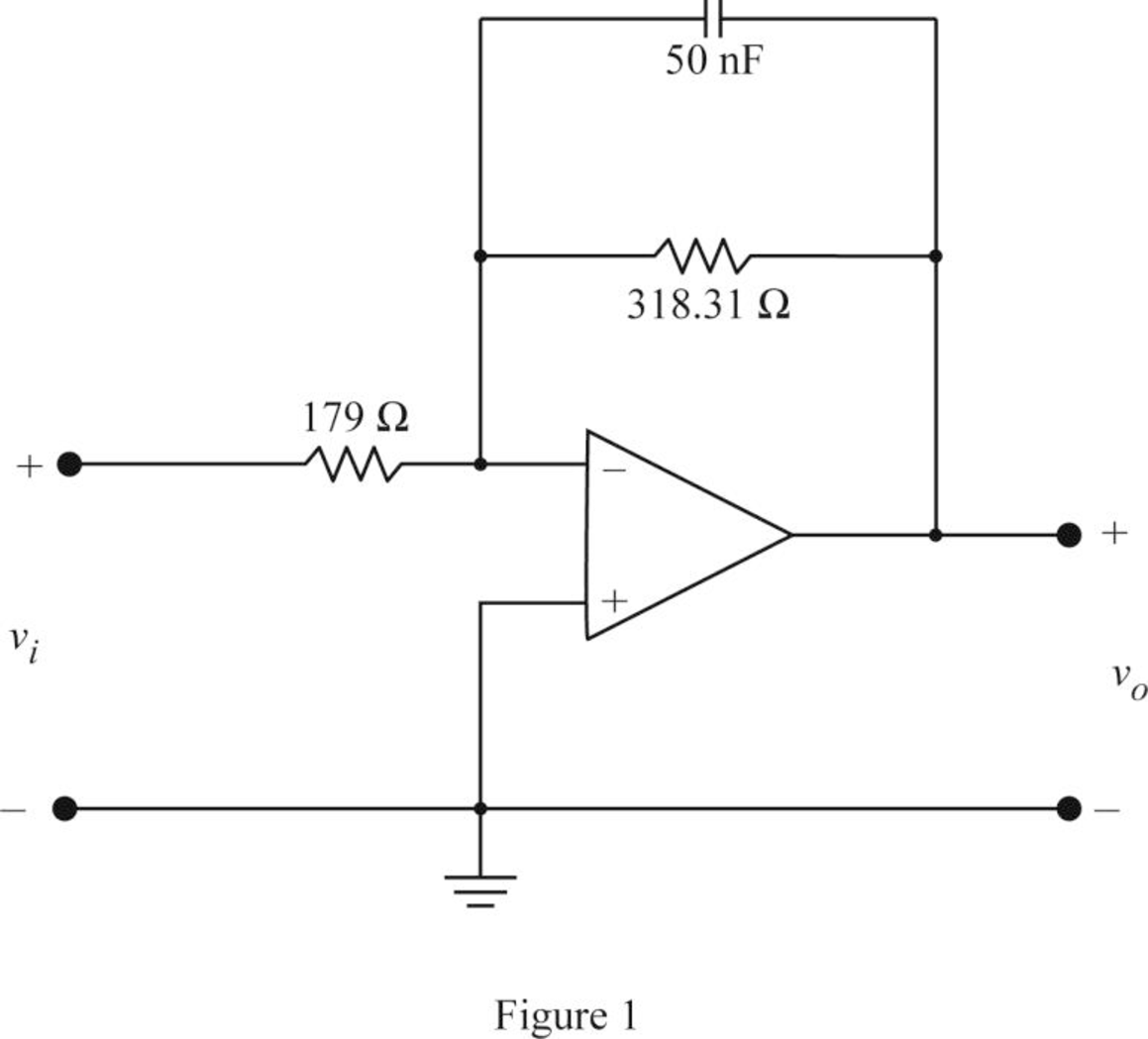
Conclusion:
Thus, the circuit diagram of designed low pass filter is shown in Figure 1.
Want to see more full solutions like this?
Chapter 15 Solutions
Electric Circuits, Student Value Edition Format: Unbound (saleable)


- The circuit shown in Fig. P12.41 was introduced inProblem 5.68. Then, a time-domain solution was sought foruout1 (t) and uout2 (t) for t ≥ 0, given that ui(t) = 10u(t) mV,VCC = 10 V for both op amps, and the two capacitors had nochange prior to t = 0. Analyze the circuit and plot uout1 (t) anduout2 (t) using the Laplace transform technique.arrow_forward12.43 For the circuit shown in Fig. P12.43, determine uout(t)given that R1 = 1 kW, R2 = 4 kW, and C = 1 μF, and(a) us(t) = 2u(t) (V),(b) us(t) = 2cos(1000t) (V),(c) us(t) = 2e−t u(t) (V).arrow_forwardPlease explain each step clearly, show your work.I am most confused on how to move the disturbance T_d(s) Thank you, I will give positive feedbackarrow_forward
- Please do question 3 and 4 of this question, the first part is submitted as a separate question due to the limit. Thank you, I will give positive feedback. Please explain each step clearlyarrow_forwardIf the circuit shown in Fig. P12.38(a) is excited by thecurrent waveform is(t) shown in Fig. P12.38(b), determine i(t)for t ≥ 0, given that R1 = 10 W, R2 = 5 W, and C = 0.02 F.arrow_forwardPlease explain each step clearly and include a proper image of what the block diagram and plot must look like. thank youarrow_forward
- A three-phase, 480-V, 60-Hz, 6-pole, Y-connected induction motor has its speed controlled by slip power. The circuit parameters are given: Rs=0.06 ohms, Rr=0.05 ohms, Xs=0.2 ohms, Xr=0.3 ohms and Xm=6 ohms. The turn ratio of the rotor to stator winding is n=0.8. The no-load losses of the motor are equal to 150 W. The rotor and stator cupper losses are equal to 249.21 W. The slip power losses are estimated to 8000W. The load torque is 173.61 N.m. at 700 rpm. The efficiency is equal to: Select one: a. 71.5% b. None of these c. 81.5% d. 91.5%arrow_forwardQuestion 1: A 3 phase, 10 kW, 1700 rpm, Y- connected 460 V, 60 Hz, 4 poles, Y-connected induction motor has the following parameters: Rr = 0.2 ohms, Xs = 0.8 ohms, Xr = 0.8 ohms, Xm = 20 ohms. The no load losses are neglected. The rotor speed is assumed to be constant equal to 1700 rpm. The V/F control method is applied. The stator resistance is negligible. If the base synchronous speed is 188.5 rad/s and the voltage frequency ratio is 1.405, then the maximum torque Tm and the corresponding speed w at 30 Hz are equal to: Select one: a. 350 N.m and 70.69 rad/s b. None of these c. 350 N.m and 164.94 rad/s d. 700 N.m and 164.94 rad/s Question 2: A 3 phase, 10 kW, 1750 rpm, Y- connected 460 V, 60 Hz, 4 poles, Y-connected induction motor has the following parameters: Rs = 0.5 Ohms, Rr = 0.3 Ohms, Xs = 0.9 Ohms, Xr = 0.9 Ohms, Xm = 25 Ohms. The no load losses are neglected. In this type of control the developed torque is proportional to the square of the statoric voltage. In this part, the…arrow_forwardPlease explain each question vlearly and explain how to do it. Thank you, I will give pos feedbackarrow_forward
- Don't use ai to answer I will report you answerarrow_forwardDon't use ai to answer I will report you answerarrow_forward12.43 For the circuit shown in Fig. P12.43, determine Vout (1) given that R₁ = 1 kQ, R₂ = 4k, and C = 1 μF, and (a) v(t)=2u(1) (V), (b) s(t)=2 cos(10001) (V), (c) vs(t) = 2e u(t) (V). R1 Us(1) + R2 Dout(1) Figure P12.43 Op-amp circuit for Problem 12.43.arrow_forward
 Introductory Circuit Analysis (13th Edition)Electrical EngineeringISBN:9780133923605Author:Robert L. BoylestadPublisher:PEARSON
 Delmar's Standard Textbook Of ElectricityElectrical EngineeringISBN:9781337900348Author:Stephen L. HermanPublisher:Cengage Learning
 Programmable Logic ControllersElectrical EngineeringISBN:9780073373843Author:Frank D. PetruzellaPublisher:McGraw-Hill Education
 Fundamentals of Electric CircuitsElectrical EngineeringISBN:9780078028229Author:Charles K Alexander, Matthew SadikuPublisher:McGraw-Hill Education
 Electric Circuits. (11th Edition)Electrical EngineeringISBN:9780134746968Author:James W. Nilsson, Susan RiedelPublisher:PEARSON
 Engineering ElectromagneticsElectrical EngineeringISBN:9780078028151Author:Hayt, William H. (william Hart), Jr, BUCK, John A.Publisher:Mcgraw-hill Education,