
Concept explainers
Types of kinematic surveys.
Answer to Problem 15.1P
Types of kinematic
1. Real time kinematic survey
2. Post process kinematic survey
Explanation of Solution
Surveying plays is an important role in all engineering projects. By measuring the horizontal and vertical direction and angle, it is an art and science to find the relative position of various valuable points or stations on the earth's surface. We prepare plans, maps, or layout by these points.
The most effective and fastest survey technique is Kinematic surveying. The relative positioning technique is used for the observation of the carrier phase shift. The cinematic survey can provide the coordinate of the points with the fastest values while the receiver is motionless or in motion.
The two types of kinematic survey are:
1. Real time kinematic survey
The Real time kinematic survey (RTK) is also referred to as the relative positioning technique that measures the position in real time using two global navigation satellite systems (GNSS). One is placed at a static point with established coordinates and is known as the base station. It carries a large frequency radio to the second unit (known as the rover) with its raw observation and the rover carries both observations to determine a position relative to the base location in real time.
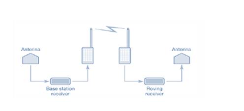
RTK surveying requires positive communication between base and rover units and works best with short baselines as the accuracy of measurements or analysis of RTK decreases as the length of the baseline increases.
2. Post process kinematic survey
A post process kinematic survey requires a base receiver that collects data at the same time rate as the rover. In the Kinematic survey of post processes, the identified coordinates should be stored in the survey controller and the observations of the raw global navigation satellite system (GNSS) are saved in the recipient until the fieldwork is completed. The data are then processed by the same software and processing techniques used in static surveys in the office.
Want to see more full solutions like this?
Chapter 15 Solutions
Elementary Surveying (14th Edition)


- For the truss shown in Fig 2, determine the nodal displacement and member forces for all elements of the truss. Assume for each member A = 0.0015 m2 and E = 200 GPa please show all working, relevant FBD's and use ID's indicated in the diagram. Note: the truss has a vertical measurement of 2m and a horizontal mesurement of 2marrow_forwardα t Αν 'A B 'B Column 1 Column 2 t t α Section A-A (for column 1) steel steel concrete concrete 2t 2t 2t 2t a Section B-B (for column 2)arrow_forward(40 pts Q: By using the PERT technique to calculate the duration of activities, as shown in the table below, Draw an activity network for the following project by using AOA method and find: 1. The project's total duration and date of completion and CP (assume the project start date 1st of May 2024). 2. The overall variance of the project? 3. The probability of completing the project in 50 days? 4. The probability of completing the project in 5th of June 2024? 5. With a probability of 90%, what is the expected duration and date for completing the project? Activity Preceding activity Optimistic duration (day) A Most likely duration (day) Pessimistic duration (day) 6 12 18 B 5 7 C 15 8 10 D 12 A 7 10 19 E C 12 15 F 18 A 7 8 G 15 A 5 9 25 H B.D.E 15 17 25 I C 14 19 30 J F 6 8 10arrow_forward
- 1. For the system shown below, calculate the power supplied to the pump if its efficiency is 82%. Methyl alcohol at 25°C is flowing at the rate of 50m³/hour. The suction line is a standard DN100 schedule 40 steel pipe, 15m long. The total length of DN50 schedule 40 steel pipe in the discharge line is 180m. Assume that the entrance from reservoir 1 is through a square-edged inlet and that the elbows are standard. The valve is a fully open globe valve. 12m Discharge line DN 50 schedule 40 steel Pump Suction line Fully open globe valve DN 100 schedule 40 steel Flow Standard elbows (2)arrow_forwardDetermine rotations at all the nodes of the beam and reactions at the supports using stiffness method. Assume support 1 and 3 are roller and support 2 is pinned, L1=1.25m, L2=3.75m and w=60kN/m. Please show all working and FBD's where relevant.arrow_forwardDraw the BMD of the beam on the compression side showing the salient values. What are the maximum bending moments of the beam? Draw the deflected shape of the beam. Assume support 1 and 3 are roller and support 2 is pinned, L1=1.25m, L2=3.75m and w=60kN/m.arrow_forward
- Size a flash and floc tank: Provide a sketch with dimensions and calculations Provide for vertical mixers Size the mixer and motor Flow Rate 33 MGD Peaking Factor 1.5 Use VDH Regs (Online) Low Temp 40 degrees High Temp = 70 degrees Redundant Tanksarrow_forwardI do not know how to solve this questionarrow_forwardI don't know how to solve this questionarrow_forward
- A national pricing service says the National price is $12.35 per unit. The adjusted price adjustment for Los Angeles is 1.15. The price adjustment for Tulsa is 0.94. What is the expected price difference between Tulsa and Los Angeles? c.$2.98 b.$2.59 d.$0.00 a.$0.21arrow_forwardPROBLEM: Design the transversely reinforced concrete deck slab shown in the cross-sectional detail below. 8" REINFORCED CONCRETE SLAB 1/4" PER FT. T 3-3% 8'-0" 8'-0" 4'-0" GIVEN: Bridge to carry two traffic lanes. Concrete strength =4.5 ksi. Grade 60 reinforcement f, = 60 ksi. Account for 25 psf future wearing surface. Assume stringers are W36 x 150. Deck has a 0.5 in integrated wearing surface.arrow_forwardPlease help me answer this questionarrow_forward

 Structural Analysis (10th Edition)Civil EngineeringISBN:9780134610672Author:Russell C. HibbelerPublisher:PEARSON
 Principles of Foundation Engineering (MindTap Cou...Civil EngineeringISBN:9781337705028Author:Braja M. Das, Nagaratnam SivakuganPublisher:Cengage Learning
 Fundamentals of Structural AnalysisCivil EngineeringISBN:9780073398006Author:Kenneth M. Leet Emeritus, Chia-Ming Uang, Joel LanningPublisher:McGraw-Hill Education
 Traffic and Highway EngineeringCivil EngineeringISBN:9781305156241Author:Garber, Nicholas J.Publisher:Cengage Learning