
Mechanics of Materials
11th Edition
ISBN: 9780137605460
Author: Russell C. Hibbeler
Publisher: Pearson Education (US)
expand_more
expand_more
format_list_bulleted
Concept explainers
Videos
Textbook Question
Chapter 14.7, Problem 87P
Determine the displacement at point C. El is constant.
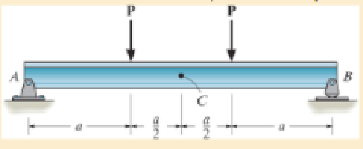
Prob. 14–87
Expert Solution & Answer

Learn your wayIncludes step-by-step video

schedule07:26
Students have asked these similar questions
What is the difference between true stress/strain and engineering stess/strain? And how do I calculate them?
A rotating shaft of 20 mm diameter is simply supported.
The shaft is loaded with a transverse load of 10 kN as shown in
the figure. The shaft is made from AISI 1095 hot-rolled steel. The
surface has been machined. The shaft operate at
temperature T = 450 °C. Consider a reliability factor of 95%.
Determine
(a) Calculate the reaction forces R, and R₂ (2 points)
(b) Draw the shear force and bending moment diagrams
and determine the maximum bending moment and
shear force. (6 points)
200 mm
20 mm
10,000 N
-50 mm-
A
Not to scale.
(c) Determine the critical location of the shaft and the maximum effective stresses. (3 points)
(d) Calculate the safety factor against yielding. Does the shaft undergo local yielding? (2 points)
(e) Determined the endurance limit, adjusted as necessary with Marin factors. (12 points)
(f) Calculate the fatigue factor of safety based on achieving infinite life. (2 points)
(g) If the fatigue factor of safety is less than 1 (hint: it should be for this problem), then…
(read image)
Chapter 14 Solutions
Mechanics of Materials
Ch. 14.2 - A material is subjected to a general state of...Ch. 14.2 - The strain-energy density for plane stress must be...Ch. 14.2 - The A-36 steel bar consists of two segments, one...Ch. 14.2 - If P = 10 kip, determine the total strain energy...Ch. 14.2 - Determine the maximum force P and the...Ch. 14.2 - Consider the thin-walled tube of Fig.5-26 . Use...Ch. 14.2 - Determine the bending strain energy in the 2-in...Ch. 14.2 - Determine the bending strain energy in the...Ch. 14.2 - Determine the bending strain energy in the simply...Ch. 14.3 - Determine the horizontal displacement of joint A....
Ch. 14.3 - Determine the vertical displacement of point S on...Ch. 14.3 - Prob. 40PCh. 14.3 - Determine the vertical displacement of end B of...Ch. 14.4 - A bar is 4 m long and has a diameter of 30 mm....Ch. 14.4 - Determine the diameter of a red brass C83400 bar...Ch. 14.4 - Prob. 44PCh. 14.4 - The collar has a weight of 50 lb and falls down...Ch. 14.4 - Prob. 52PCh. 14.4 - The composite aluminum 2014T6 bar is made from two...Ch. 14.4 - The composite aluminum 2014-T6 bar is made from...Ch. 14.4 - If the beam is a W1015, determine the maximum...Ch. 14.4 - If the maximum allowable bending stress for the...Ch. 14.4 - A 40-lb weight is dropped from a height of h = 2...Ch. 14.4 - The car bumper is made of...Ch. 14.6 - Determine the vertical displacement of joint A....Ch. 14.6 - Determine the vertical displacement of joint E....Ch. 14.6 - Determine the horizontal displacement of joint B...Ch. 14.6 - Determine the vertical displacement of joint C of...Ch. 14.7 - Determine the displacement at point C. El is...Ch. 14.7 - The beam is made of southern pine for which Ep =...Ch. 14.7 - Determine the displacement at point C. El is...Ch. 14.7 - Determine the slope at point C. El is constant....Ch. 14.7 - Determine the slope at point A. El is constant....Ch. 14.7 - Determine the displacement of point C of the beam...Ch. 14.7 - Determine the slope at B of the beam made from...Ch. 14.7 - The beam is made of Douglas fir. Determine the...Ch. 14.7 - Determine the displacement at pulley B. The A992...Ch. 14.7 - Determine the displacement at point C of the...Ch. 14.7 - Determine the slope at A of the shaft. El is...Ch. 14.7 - Determine the slope at A of the 2014T6 aluminum...Ch. 14.7 - Prob. 104PCh. 14.7 - Prob. 105PCh. 14.7 - Determine the displacement at point C of the W14 ...Ch. 14.7 - Determine the slope at A of the W14 26 beam made...Ch. 14.7 - Determine the slope at C of the overhang white...Ch. 14.7 - Determine the displacement at point D of the...Ch. 14.7 - Determine the maximum deflection of the beam...Ch. 14.7 - The beam is made of oak, for which Eo = 11 GPa....Ch. 14.7 - Determine the slope of the shaft at the bearing...Ch. 14.7 - The L-shaped frame is made from two segments, each...Ch. 14.7 - Determine the vertical displacement of the ring at...Ch. 14.7 - Determine the horizontal displacement at the...Ch. 14.9 - Solve Prob. 1473 using Castiglianos theorem. 1473....Ch. 14.9 - Solve Prob. 1474 using Castiglianos theorem. 1474....Ch. 14.9 - Prob. 125PCh. 14.9 - Prob. 126PCh. 14.9 - Prob. 127PCh. 14.9 - Solve Prob. 1478 using Castiglianos theorem. 1478....Ch. 14.9 - Solve Prob. 1481 using Castiglianos theorem. 1481....Ch. 14.9 - Solve Prob. 1482 using Castiglianos theorem. 1482....Ch. 14.9 - Solve Prob. 1485 using Castiglianos theorem. 1485....Ch. 14.9 - Solve Prob. 1486 using Castiglianos theorem. 1486....Ch. 14.10 - Solve Prob. 1490 using Castiglianos theorem. 1490....Ch. 14.10 - Solve Prob. 1491 using Castiglianos theorem. 1491....Ch. 14.10 - Prob. 135PCh. 14.10 - Solve Prob. 1493 using Castiglianos theorem. 1493....Ch. 14.10 - Solve Prob. 1495 using Castiglianos theorem. 1495....Ch. 14.10 - Solve Prob. 1496 using Castiglianos theorem. 1496....Ch. 14.10 - Prob. 139PCh. 14.10 - Prob. 140PCh. 14.10 - Prob. 141PCh. 14 - A = 2300 mm2, I = 9.5(106) mm4. R141Ch. 14 - If the spring at B has a stiffness k = 200 kN/m....Ch. 14 - The spring at B has a stiffness k = 200 kN/m....Ch. 14 - If they each have a diameter of 30 mm, determine...Ch. 14 - and a length of 10 in. It is struck by a hammer...Ch. 14 - Determine the total axial and bending strain...Ch. 14 - The truss is made from A992 steel rods each having...Ch. 14 - The truss is made from A992 steel rods each having...Ch. 14 - El is constant. Use the method of virtual work....Ch. 14 - using Castiglianos theorem. R149. The cantilevered...
Additional Engineering Textbook Solutions
Find more solutions based on key concepts
Give an example of each of the following, other than those described in this chapter, and clearly explain why y...
Modern Database Management
Find the no-load value of υo in the circuit shown.
Find υo when RL is 150 Ω.
How much power is dissipated in th...
Electric Circuits. (11th Edition)
The data shown in the following graph was collected during testing of an electromagnetic mass driver. The energ...
Thinking Like an Engineer: An Active Learning Approach (4th Edition)
Fill in the blanks in each of the following statements: A(n)and a(n)begin and end the body of every method.
Java How to Program, Early Objects (11th Edition) (Deitel: How to Program)
How is the hydrodynamic entry length defined for flow in a pipe? Is the entry length longer in laminar or turbu...
Fluid Mechanics: Fundamentals and Applications
Personnel Report NOTE: This assignment assumes you have already completed Programming Challenges 4 and 5. Write...
Starting Out with C++ from Control Structures to Objects (9th Edition)
Knowledge Booster


Learn more about
Need a deep-dive on the concept behind this application? Look no further. Learn more about this topic, mechanical-engineering and related others by exploring similar questions and additional content below.Similar questions
- (read image)arrow_forward(read image)arrow_forward6: Refer to the figure.Given: W1 = 200 kN/m; W2 = 300 kN/m; L1 = 2 m; L2 = 3 m; L3 = 2 m(a) Calculate the total length L so that the resulting upward pressureq is uniform. (b) draw the shear and moment diagram and determinethe maximum shear, maximum positive and negative bendingmoments.arrow_forward
- A six cylinder, four-stroke diesel engine develops a power of 200 kW at 2000 rpm. The bsfc is 0.2 kW/kg h of fuel with 34.9° API. The fuel is injected at an average pressure of 350 bar and the pressure in the combustion chamber is 40 bar. Assuming Ca for injector 0.75 and the atmospheric pressure 1 bar. Determine the period of injection in seconds if the total orifice area required per injector is 0.4876 × 10⁻⁶ m².arrow_forwardTrieed a detailed drawing Win explanatio LL Antsmi 1981x pu + 96252 اه 6. The Pre-combustion chamber design engines employ nozzle type commonly referred to as a ....... a. inward-opening nozzle b. multiple-hole nozzle. c. pintle nozzle. d. none of these. 7. If the temperature of the spark plug tip is less than 350 °C, ......... a. the plug might not work. b. the carbon deposits would increase. 8. Port injection sprays fuel....... c. pre-ignition will occur. d. none of these. a. towards the intake valve. b. in the engine cylinder. c. in the throttle body assembly. d. none of these. 9. When the fuel-air mixture changed from best power to a richer ratio, the spark advance should be........ a. increased. b. decreased. c. left unchanged. d. none of these. d. none of these. 10. Spark plugs are classified as hot plugs and cold plugs depending upon ........ a. spark gap. b. the type of plug c. the operating temperature insulator. range of the electrode tip. ---20125 750 x2.01 SP 5.arrow_forwardA 1. How does the octane number (O.N.) of the fuel a. Higher ignition advance is required for a high O.N. fuel. b. Higher ignition retard is required for a high O.N. fuel. affect spark ing:d. Nou does not affect spark timing. c. The octane number 2. How does the ignition system account for load change? these. of a. The throttle b. The vacuum ignition governor c. The mechanism of d. None of is wide opened. provide additional spark advance at part throttle positions. centrifugal advance does the job. these. 3. In the common rail fuel system the fuel is metered by ........ a. low pressure pump. b. injectors. c. high pressure pump. d. none of these. 4.......... is the time period, measured in degrees of cam rotation, during which the contact points remain closed between each opening. a. Distributor. b. Dwell. c. ECU. d. none of these. 5. The trigger wheel in TCI system replaces the ......... used in a contact breaker distributor. a. pickup coil. b. distributor cam. c. condenser. 750 x2.01…arrow_forward
- a い يكا 4 +91- pu Answer the following statements by true or false, giving the reason for your answer: 1. Injection pressure in CI engines should be sufficiently high. 2. The purpose of the condenser in battery ignition system is to prevent spark in the ignition coil assembly. 3. An idling engine requires lean mixture of fuel and air. 4. Factors which decide optimum engine firing order are engine vibration, engine cooling and back pressure. 5. It is the duty of the header to control over speeding during CI engine operation when drastic reduction in load occurs. ---20125 750 x2.01 SParrow_forward6. The Pre-combustion chamber design engines employ nozzle type commonly referred to as a a. inward-opening nozzle b. multiple-hole nozzle. c. pintle nozzle. d. none of these. 7. If the temperature of the spark plug tip is less than 350 °C, ........ a. the plug might b. the carbon deposits not work. would increase. c. pre-ignition will occur. d. none of these. 8. Port injection sprays fuel........ a. towards the intake valve. b. in the engine cylinder. c. in the throttle body d. none of assembly. these. 9. When the fuel-air mixture changed from best power to a richer ratio, the spark advance should be ........ a. increased. b. decreased. c. left unchanged. d. none of these. 10. Spark plugs are classified as hot plugs and cold plugs depending upon a. spark gap. b. the type of plug c. the operating temperature d. none of these. range of the electrode tip. insulator.arrow_forward1: A H = 6 m cantilever retaining wall is subjected to a soil pressurelinearly varying from zero at the top to 90 kPa at the bottom. As an additionalsupport, it is anchored at depth y = 2 m. with maximum tension equal to 25kN. Assume that the stem provides fully retrained support. Draw the shearand moment diagram of the wall to calculate the following: (a) Maximumpositive bending moment per linear meter; (b) maximum negative bendingmoment per linear meter; (c) maximum shear force per linear meter.arrow_forward
- CORRECT AND DETAILED SOLUTION WITH COMPLETE FBD ONLY. I WILL UPVOTE. 9: The beam shown has a width of 80 mm and its allowable bending stress is not to exceed 120 MPa. Calculatethe required depth of the beam.arrow_forwardPROBLEM 4: A pre-stressed concrete pile of length L (m) is to be picked up by crane cables at two points, both equidistant from the ends. If the concrete pile has a cross-sectional area of A (m²) and concrete has unit weight of Yc (kN/m³), calculate the distance of the pick-up points from the end in terms of pile length. (Hint: to minimize the absolute maximum moment, the maximum negative and maximum negative moments should be equal)arrow_forwardCorrect and detailed solution only. Complete fbd. I will upvote.arrow_forward
arrow_back_ios
SEE MORE QUESTIONS
arrow_forward_ios
Recommended textbooks for you
 International Edition---engineering Mechanics: St...Mechanical EngineeringISBN:9781305501607Author:Andrew Pytel And Jaan KiusalaasPublisher:CENGAGE L
International Edition---engineering Mechanics: St...
Mechanical Engineering
ISBN:9781305501607
Author:Andrew Pytel And Jaan Kiusalaas
Publisher:CENGAGE L
Mechanical Engineering: Centroids & Center of Gravity (1 of 35) What is Center of Gravity?; Author: Michel van Biezen;https://www.youtube.com/watch?v=Tkyk-G1rDQg;License: Standard Youtube License