Mechanics of Materials, Student Value Edition Plus Mastering Engineering with Pearson eText -- Access Card Package (10th Edition)
10th Edition
ISBN: 9780134326054
Author: Russell C. Hibbeler
Publisher: PEARSON
expand_more
expand_more
format_list_bulleted
Concept explainers
Videos
Textbook Question
Chapter 14.6, Problem 14.83P
Determine the vertical displacement of joint A. The truss is made from A992 steel rods having a diameter of 30 mm.
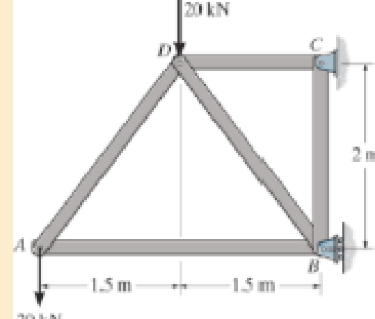
Probs. 14–83/84
Expert Solution & Answer
Want to see the full answer?
Check out a sample textbook solution
Students have asked these similar questions
my ID# 016948724. Please solve this problem step by step
My ID# 016948724 please find the forces for Fx=0: fy=0: fz=0: please help me to solve this problem step by step
My ID# 016948724 please solve the proble step by step find the forces fx=o: fy=0; fz=0; and find shear moment and the bending moment diagran please draw the diagram for the shear and bending moment
Chapter 14 Solutions
Mechanics of Materials, Student Value Edition Plus Mastering Engineering with Pearson eText -- Access Card Package (10th Edition)
Ch. 14.2 - A material is subjected to a general state of...Ch. 14.2 - The strain-energy density for plane stress must be...Ch. 14.2 - The A-36 steel bar consists of two segments, one...Ch. 14.2 - Determine the torsional strain energy in the A992...Ch. 14.2 - Using bolts of the same material and...Ch. 14.2 - If P = 60 kN, determine the total strain energy...Ch. 14.2 - Determine the maximum force P and the...Ch. 14.2 - Determine the torsional strain energy in the A992...Ch. 14.2 - Determine the torsional strain energy in the A-36...Ch. 14.2 - The shaft assembly is fixed at C. The hollow...
Ch. 14.2 - Determine the total axial and bending strain...Ch. 14.2 - If P = 10 kip, determine the total strain energy...Ch. 14.2 - Determine the maximum force P and the...Ch. 14.2 - Consider the thin-walled tube of Fig.5-26 . Use...Ch. 14.2 - Determine the bending strain energy in the A992...Ch. 14.2 - Determine the bending strain energy in the beam....Ch. 14.2 - Prob. 14.17PCh. 14.2 - Prob. 14.18PCh. 14.2 - Determine the bending strain energy in the 2-in...Ch. 14.2 - Determine the total strain energy in the steel...Ch. 14.2 - Determine the bending strain energy in the beam....Ch. 14.2 - The bolt has a diameter of 10 mm, and the arm AB...Ch. 14.2 - Determine the bending strain energy in the...Ch. 14.2 - Determine the bending strain energy in the simply...Ch. 14.3 - Determine the vertical displacement of joint D. AE...Ch. 14.3 - Determine the horizontal displacement of joint C....Ch. 14.3 - Determine the horizontal displacement of joint A....Ch. 14.3 - AE is constant. Prob. 1428Ch. 14.3 - Determine the vertical displacement of point C of...Ch. 14.3 - Determine the vertical displacement of end B of...Ch. 14.3 - Determine the vertical displacement of point S on...Ch. 14.3 - EI is constant. Prob. 1432Ch. 14.3 - The A992 steel bars are pin connected at C and D....Ch. 14.3 - The A992 steel bars are pin connected at C. If...Ch. 14.3 - Determine the slope of the beam at the pin support...Ch. 14.3 - The cantilevered beam has a rectangular...Ch. 14.3 - The rod has a circular cross section with a moment...Ch. 14.3 - The rod has a circular cross section with a moment...Ch. 14.3 - Determine the vertical displacement of point B on...Ch. 14.3 - Prob. 14.40PCh. 14.3 - Determine the vertical displacement of end B of...Ch. 14.4 - A bar is 4 m long and has a diameter of 30 mm....Ch. 14.4 - Determine the diameter of a red brass C83400 bar...Ch. 14.4 - Prob. 14.44PCh. 14.4 - The collar has a weight of 50 lb and falls down...Ch. 14.4 - The collar has a weight of 50 lb and falls down...Ch. 14.4 - Prob. 14.47PCh. 14.4 - Prob. 14.48PCh. 14.4 - Prob. 14.49PCh. 14.4 - Prob. 14.50PCh. 14.4 - The A-36 steel bolt is required to absorb the...Ch. 14.4 - Prob. 14.52PCh. 14.4 - The composite aluminum 2014T6 bar is made from two...Ch. 14.4 - The composite aluminum 2014-T6 bar is made from...Ch. 14.4 - When the 100-lb block is at h = 3 ft above the...Ch. 14.4 - If the bar has a diameter of 20 mm, determine the...Ch. 14.4 - The collar has a mass of 5 kg and falls dawn the...Ch. 14.4 - The tugboat has a weight of 120 000 lb and is...Ch. 14.4 - The W10 12 beam is made from A-36 steel and is...Ch. 14.4 - The weight of 175 lb is dropped from a height of 4...Ch. 14.4 - The weight of 175 lb, is dropped from a height of...Ch. 14.4 - Determine the maximum height h from which an 80-lb...Ch. 14.4 - The 80-lb weight is dropped from rest at a height...Ch. 14.4 - The 75-lb block has a downward velocity of 2 ft/s...Ch. 14.4 - The 75-lb block has a downward velocity of 2 ft/s...Ch. 14.4 - Prob. 14.66PCh. 14.4 - The overhang beam is made of 2014T6 aluminum....Ch. 14.4 - If the beam is a W1015, determine the maximum...Ch. 14.4 - If the maximum allowable bending stress for the...Ch. 14.4 - A 40-lb weight is dropped from a height of h = 2...Ch. 14.4 - The car bumper is made of...Ch. 14.6 - Determine the vertical displacement of joint A....Ch. 14.6 - Determine the horizontal displacement of joint B....Ch. 14.6 - Determine the vertical displacement of joint B....Ch. 14.6 - Determine the vertical displacement of joint B....Ch. 14.6 - Determine the vertical displacement of joint E....Ch. 14.6 - Determine the horizontal displacement of joint B....Ch. 14.6 - Determine the vertical displacement of joint B....Ch. 14.6 - Determine the horizontal displacement of joint B...Ch. 14.6 - Determine the vertical displacement of joint C of...Ch. 14.6 - Determine the horizontal displacement of joint C....Ch. 14.6 - Determine the vertical displacement of joint D....Ch. 14.6 - Determine the vertical displacement of joint A....Ch. 14.6 - The truss is made from A992 steel rods having a...Ch. 14.6 - Determine the horizontal displacement of joint D....Ch. 14.6 - Determine the horizontal displacement of joint E....Ch. 14.7 - Determine the displacement at point C. El is...Ch. 14.7 - The beam is made of southern pine for which Ep =...Ch. 14.7 - Determine the displacement at point C. El is...Ch. 14.7 - Determine the slope at point C. El is constant....Ch. 14.7 - Determine the slope at point A. El is constant....Ch. 14.7 - Determine the displacement of point C of the beam...Ch. 14.7 - Determine the slope at B of the beam made from...Ch. 14.7 - The beam is made of Douglas fir. Determine the...Ch. 14.7 - Determine the displacement at pulley B. The A992...Ch. 14.7 - The A992 steel beam has a moment of inertia of I =...Ch. 14.7 - The A992 steel beam has a moment of inertia of I =...Ch. 14.7 - The A992 structural steel beam has a moment of...Ch. 14.7 - Determine the displacement at point C of the...Ch. 14.7 - Determine the slope at A of the shaft. El is...Ch. 14.7 - Determine the slope of end C of the overhang beam....Ch. 14.7 - Determine the displacement of point D of the...Ch. 14.7 - Determine the slope at A of the 2014T6 aluminum...Ch. 14.7 - Prob. 14.104PCh. 14.7 - Prob. 14.105PCh. 14.7 - Determine the displacement at point C of the W14 ...Ch. 14.7 - Determine the slope at A of the W14 26 beam made...Ch. 14.7 - Determine the slope at A. El is constant. Prob....Ch. 14.7 - Determine the slope at C of the overhang white...Ch. 14.7 - Determine the displacement at point D of the...Ch. 14.7 - Determine the maximum deflection of the beam...Ch. 14.7 - The beam is made of oak, for which Eo = 11 GPa....Ch. 14.7 - Determine the slope of the shaft at the bearing...Ch. 14.7 - Determine the horizontal and vertical...Ch. 14.7 - Beam AB has a square cross section of 100 mm by...Ch. 14.7 - Beam AB has a square cross section of 100 mm by...Ch. 14.7 - Bar ABC has a rectangular cross section of 300 mm...Ch. 14.7 - Bar ABC has a rectangular cross section of 300 mm...Ch. 14.7 - The L-shaped frame is made from two segments, each...Ch. 14.7 - The L-shaped frame is made from two segments, each...Ch. 14.7 - Determine the vertical displacement of the ring at...Ch. 14.7 - Determine the horizontal displacement at the...Ch. 14.9 - Solve Prob. 1473 using Castiglianos theorem. 1473....Ch. 14.9 - Solve Prob. 1474 using Castiglianos theorem. 1474....Ch. 14.9 - Prob. 14.125PCh. 14.9 - Prob. 14.126PCh. 14.9 - Prob. 14.127PCh. 14.9 - Solve Prob. 1478 using Castiglianos theorem. 1478....Ch. 14.9 - Solve Prob. 1481 using Castiglianos theorem. 1481....Ch. 14.9 - Solve Prob. 1482 using Castiglianos theorem. 1482....Ch. 14.9 - Solve Prob. 1485 using Castiglianos theorem. 1485....Ch. 14.9 - Solve Prob. 1486 using Castiglianos theorem. 1486....Ch. 14.10 - Solve Prob. 1490 using Castiglianos theorem. 1490....Ch. 14.10 - Solve Prob. 1491 using Castiglianos theorem. 1491....Ch. 14.10 - Prob. 14.135PCh. 14.10 - Solve Prob. 1493 using Castiglianos theorem. 1493....Ch. 14.10 - Solve Prob. 1495 using Castiglianos theorem. 1495....Ch. 14.10 - Solve Prob. 1496 using Castiglianos theorem. 1496....Ch. 14.10 - Prob. 14.139PCh. 14.10 - Prob. 14.140PCh. 14.10 - Prob. 14.141PCh. 14.10 - Solve Prob. 14119 using Castiglianos theorem....Ch. 14.10 - Prob. 14.143PCh. 14.10 - Solve Prob. 14105 using Castiglianos theorem....Ch. 14 - A = 2300 mm2, I = 9.5(106) mm4. R141Ch. 14 - If the spring at B has a stiffness k = 200 kN/m....Ch. 14 - The spring at B has a stiffness k = 200 kN/m....Ch. 14 - If they each have a diameter of 30 mm, determine...Ch. 14 - and a length of 10 in. It is struck by a hammer...Ch. 14 - Determine the total axial and bending strain...Ch. 14 - The truss is made from A992 steel rods each having...Ch. 14 - The truss is made from A992 steel rods each having...Ch. 14 - El is constant. Use the method of virtual work....Ch. 14 - using Castiglianos theorem. R149. The cantilevered...
Additional Engineering Textbook Solutions
Find more solutions based on key concepts
Look at the following description of a problem domain:
Starting Out with Java: From Control Structures through Data Structures (4th Edition) (What's New in Computer Science)
Write a summary list of the problem-solving steps identified in the chapter, using your own words.
BASIC BIOMECHANICS
Why is the study of database technology important?
Database Concepts (8th Edition)
17–1C A high-speed aircraft is cruising in still air. How does the temperature of air at the nose of the aircra...
Thermodynamics: An Engineering Approach
What types of coolant are used in vehicles?
Automotive Technology: Principles, Diagnosis, And Service (6th Edition) (halderman Automotive Series)
How does a computers main memory differ from its auxiliary memory?
Java: An Introduction to Problem Solving and Programming (8th Edition)
Knowledge Booster


Learn more about
Need a deep-dive on the concept behind this application? Look no further. Learn more about this topic, mechanical-engineering and related others by exploring similar questions and additional content below.Similar questions
- My ID#016948724 please solve this problems and show me every step clear to follow pleasearrow_forwardMy ID# 016948724arrow_forwardPlease do not use any AI tools to solve this question. I need a fully manual, step-by-step solution with clear explanations, as if it were done by a human tutor. No AI-generated responses, please.arrow_forward
- Please do not use any AI tools to solve this question. I need a fully manual, step-by-step solution with clear explanations, as if it were done by a human tutor. No AI-generated responses, please.arrow_forwardPlease do not use any AI tools to solve this question. I need a fully manual, step-by-step solution with clear explanations, as if it were done by a human tutor. No AI-generated responses, please.arrow_forward[Q2]: The cost information supplied by the cost accountant is as follows:Sales 20,00 units, $ 10 per unitCalculate the (a/ newsale guantity and (b) new selling price to earn the sameVariable cost $ 6 per unit, Fixed Cost $ 30,000, Profit $ 50,000profit ifi) Variable cost increases by $ 2 per unitil) Fixed cost increase by $ 10,000Ili) Variable cost increase by $ 1 per unit and fixed cost reduces by $ 10,000arrow_forward
- can you please help me perform Visual Inspection and Fractography of the attatched image: Preliminary examination to identify the fracture origin, suspected fatigue striation, and corrosion evidences.arrow_forwardcan you please help[ me conduct Causal Analysis (FTA) on the scenario attatched: FTA diagram which is a fault tree analysis diagram will be used to gain an overview of the entire path of failure from root cause to the top event (i.e., the swing’s detachment) and to identify interactions between misuse, material decay and inspection errors.arrow_forwardhi can you please help me in finding the stress intensity factor using a k-calcluator for the scenario attathced in the images.arrow_forward
arrow_back_ios
SEE MORE QUESTIONS
arrow_forward_ios
Recommended textbooks for you
 Elements Of ElectromagneticsMechanical EngineeringISBN:9780190698614Author:Sadiku, Matthew N. O.Publisher:Oxford University Press
 Mechanics of Materials (10th Edition)Mechanical EngineeringISBN:9780134319650Author:Russell C. HibbelerPublisher:PEARSON
 Thermodynamics: An Engineering ApproachMechanical EngineeringISBN:9781259822674Author:Yunus A. Cengel Dr., Michael A. BolesPublisher:McGraw-Hill Education
 Control Systems EngineeringMechanical EngineeringISBN:9781118170519Author:Norman S. NisePublisher:WILEY
 Mechanics of Materials (MindTap Course List)Mechanical EngineeringISBN:9781337093347Author:Barry J. Goodno, James M. GerePublisher:Cengage Learning
 Engineering Mechanics: StaticsMechanical EngineeringISBN:9781118807330Author:James L. Meriam, L. G. Kraige, J. N. BoltonPublisher:WILEY
Elements Of Electromagnetics
Mechanical Engineering
ISBN:9780190698614
Author:Sadiku, Matthew N. O.
Publisher:Oxford University Press
Mechanics of Materials (10th Edition)
Mechanical Engineering
ISBN:9780134319650
Author:Russell C. Hibbeler
Publisher:PEARSON
Thermodynamics: An Engineering Approach
Mechanical Engineering
ISBN:9781259822674
Author:Yunus A. Cengel Dr., Michael A. Boles
Publisher:McGraw-Hill Education
Control Systems Engineering
Mechanical Engineering
ISBN:9781118170519
Author:Norman S. Nise
Publisher:WILEY
Mechanics of Materials (MindTap Course List)
Mechanical Engineering
ISBN:9781337093347
Author:Barry J. Goodno, James M. Gere
Publisher:Cengage Learning
Engineering Mechanics: Statics
Mechanical Engineering
ISBN:9781118807330
Author:James L. Meriam, L. G. Kraige, J. N. Bolton
Publisher:WILEY
Engineering Basics - Statics & Forces in Equilibrium; Author: Solid Solutions - Professional Design Solutions;https://www.youtube.com/watch?v=dQBvQ2hJZFg;License: Standard YouTube License, CC-BY