Engineering Mechanics: Dynamics; Modified Mastering Engineering with Pearson eText -- Standalone Access Card -- for Engineering Mechanics: Dynamics (14th Edition)
14th Edition
ISBN: 9780134229294
Author: HIBBELER
Publisher: PEARSON
expand_more
expand_more
format_list_bulleted
Concept explainers
Videos
Textbook Question
Chapter 14.5, Problem 1CP
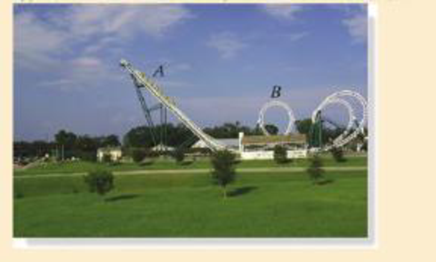
Determine the approximate normal force it exerts on the track at B. Also determine its approximate acceleration at this point. Use numerical data, and take scaled measurements from the photo with a known height at A.
Expert Solution & Answer
Want to see the full answer?
Check out a sample textbook solution
Students have asked these similar questions
Please solve this problem as soon as possible My ID# 016948724
The gears shown in the figure have a diametral pitch of 2 teeth per inch and a 20° pressure angle.
The pinion rotates at 1800 rev/min clockwise and transmits 200 hp through the idler pair to gear
5 on shaft c. What forces do gears 3 and 4 transmit to the idler shaft?
TS
I
y
18T
32T
This
a
12
x
18T
C
48T
5
Question 1. Draw 3 teeth for the following pinion and gear respectively. The teeth
should be drawn near the pressure line so that the teeth from the pinion should
mesh those of the gear. Drawing scale (1:1). Either a precise hand drawing or
CAD drawing is acceptable. Draw all the trajectories of the involute lines and the
circles.
Specification: 18tooth pinion and 30tooth gear. Diameter pitch=P=6 teeth /inch.
Pressure angle:20°, 1/P for addendum (a) and 1.25/P for dedendum (b). For fillet,
c=b-a.
Chapter 14 Solutions
Engineering Mechanics: Dynamics; Modified Mastering Engineering with Pearson eText -- Standalone Access Card -- for Engineering Mechanics: Dynamics (14th Edition)
Ch. 14.3 - Determine the work of the force when it displaces...Ch. 14.3 - Determine the kinetic energy of the 10-kg block.Ch. 14.3 - The spring is placed between the wall and the...Ch. 14.3 - If the motor exerts a constant force of 300 N on...Ch. 14.3 - The crate is initially at rest on the ground.Ch. 14.3 - If the drag force of the parachute can be...Ch. 14.3 - When s = 0.5 m, the spring is unstretched and the...Ch. 14.3 - The 5-lb collar is pulled by a cord that passes...Ch. 14.3 - The 20-kg crate is subjected to a force having a...Ch. 14.3 - If the relation between the force and deflection...
Ch. 14.3 - If it is originally at rest, determine the...Ch. 14.3 - If it is originally at rest, determine the...Ch. 14.3 - Determine the required height h of the roller...Ch. 14.3 - How far will the truck skid if it is traveling 80...Ch. 14.3 - Show that this is so, by considering the 10-kg...Ch. 14.3 - A force of F = 250 N is applied to the end at B....Ch. 14.3 - If the block has a mass of 20 kg and is suspended...Ch. 14.3 - Determine how far the block must slide before its...Ch. 14.3 - If the 6-kg collar is orginally at rest, determine...Ch. 14.3 - Select the proper value of k so that the maximum...Ch. 14.3 - Determine the speed of the brick just before it...Ch. 14.3 - Determine the speed of block A after it moves 5 ft...Ch. 14.3 - If the kinetic coefficient of friction between the...Ch. 14.3 - Determine the angle at which the box leaves the...Ch. 14.3 - If the cord is subjected to a constant force of F=...Ch. 14.3 - Determine the maximum distance A will fall before...Ch. 14.3 - If the cord is subjected to a constant force of F=...Ch. 14.3 - The barrier stopping force is measured versus the...Ch. 14.3 - The coefficient of kinetic friction between both...Ch. 14.3 - If the coefficient of kinetic friction between the...Ch. 14.3 - The 8-Kg block is moving with an initial speed of...Ch. 14.3 - At a given instant the 10-lb block A is moving...Ch. 14.3 - The 5-lb cylinder is falling from A with a speed...Ch. 14.3 - The propelling action is obtained by drawing the...Ch. 14.3 - By design the car cannot fall off the track,...Ch. 14.3 - If the coefficient of kinetic friction along AB is...Ch. 14.3 - Prob. 29PCh. 14.3 - If the can is prevented from moving, determine the...Ch. 14.3 - Determine the placement R of the can from the end...Ch. 14.3 - If it starts from rest when the attached spring is...Ch. 14.3 - Neglect the size of the block.Ch. 14.3 - As shown, the spring is confined by the plate P...Ch. 14.3 - Determine his speed when he reaches point B on the...Ch. 14.3 - As shown, it is confined by the plate and wall...Ch. 14.3 - If the track is to be designed so that the...Ch. 14.3 - Neglect friction.Ch. 14.3 - Neglect friction and the size of the pulley.Ch. 14.3 - Neglect friction and the size of the pulley.Ch. 14.3 - An elastic cord having a stiffness k = 2 lb/ft is...Ch. 14.4 - In initially, the block is at rest.Ch. 14.4 - When s = 0, the 20-kg block is moving at v = 1...Ch. 14.4 - The load weighs 100 lb and the efficiency of the...Ch. 14.4 - If the block is traveling up the inclined plane...Ch. 14.4 - determine the power input to the motor, which...Ch. 14.4 - which is increasing at a rate of aP = 6 m/s2....Ch. 14.4 - Assuming the wheels do not slip on the ground,...Ch. 14.4 - Determine the power Input for a motor necessary to...Ch. 14.4 - If mechanical friction and wind resistance are...Ch. 14.4 - manufactures a turbojet engine that is placed in a...Ch. 14.4 - If the car is brought to a stop, determine how...Ch. 14.4 - If the steps are 125 mm high and 250 mm in length,...Ch. 14.4 - Determine the power generated. How long would a...Ch. 14.4 - Determine the maximum power that must be supplied...Ch. 14.4 - The cable is tied to the top of the oil rig, wraps...Ch. 14.4 - The motor has an efficiency of = 0.65.Ch. 14.4 - The 50-lb crate is given a speed of 10ft/s in t =...Ch. 14.4 - The engine has a running efficiency = 0.68.Ch. 14.4 - If the drag resistance on the car due to the wind...Ch. 14.4 - Hoisting is provided by the motor M and the 60-kg...Ch. 14.4 - If the rod is smooth, determine the power...Ch. 14.4 - Determine the power developed by the power...Ch. 14.4 - A force F = (40 + s2) lb, where sis in ft, acts on...Ch. 14.4 - If the steps are 125 mm high and 250 mm in length,...Ch. 14.4 - If the escalator in Prob.14-46 is not moving,...Ch. 14.4 - Neglect drag and rolling resistance, and the loss...Ch. 14.4 - Also, the velocity of the athletes arm acting in...Ch. 14.4 - Prob. 63PCh. 14.4 - If the motor draws in the cable at a constant rate...Ch. 14.5 - If a force F = (60t2) N, where t is in seconds, is...Ch. 14.5 - Determine the potential energy of the block that...Ch. 14.5 - Determine the potential energy in the spring that...Ch. 14.5 - The 2-kg pendulum bob is released from rest when...Ch. 14.5 - The 2-kg package leaves the conveyor belt at A...Ch. 14.5 - The 2-kg collar is given a downward velocity of 4...Ch. 14.5 - Determine the speed of the collar when it strikes...Ch. 14.5 - Determine the compression of each spring when the...Ch. 14.5 - If the guide rod is smooth, determine the speed of...Ch. 14.5 - If she is swinging to a maximum height defined by ...Ch. 14.5 - If it is then released, determine the maximum...Ch. 14.5 - Determine the speed of the collar when it reaches...Ch. 14.5 - Determine its speed when its center reaches point...Ch. 14.5 - If it is released from rest when = 0, determine...Ch. 14.5 - If the car is released from rest, determine its...Ch. 14.5 - Prob. 72PCh. 14.5 - If it is released from rest at the top of the hill...Ch. 14.5 - Determine the speed of each block when B descends...Ch. 14.5 - Determine the distance B must descend in order for...Ch. 14.5 - The spring has a stiffness k =50 N/m and an...Ch. 14.5 - Neglect friction.Ch. 14.5 - If it is attached to the 3-kg smooth collar and...Ch. 14.5 - Prob. 79PCh. 14.5 - If the arm is pulled back such that s = 100 mm and...Ch. 14.5 - If the arm is pulled back such that s = 100 mm and...Ch. 14.5 - For the calculation, locate the datum at r . Also,...Ch. 14.5 - Prob. 83PCh. 14.5 - The spring has an unstretched length of 1 m.Ch. 14.5 - A 60-kg satellite travels in free flight along an...Ch. 14.5 - If friction and air resistance can be neglected,...Ch. 14.5 - If the mass of the bumpers A and B can be...Ch. 14.5 - If the collar moves over the smooth rod, determine...Ch. 14.5 - When the 6-kg box reaches point A it has a speed...Ch. 14.5 - Determine the normal force the box exerts on the...Ch. 14.5 - Determine how high the box reaches up the surface...Ch. 14.5 - Determine the cars velocity and the normal force...Ch. 14.5 - The 10-kg sphere C is released from rest when =...Ch. 14.5 - If the chain is released from rest from the...Ch. 14.5 - Each spring has a stiffness k = 40 N/m and an...Ch. 14.5 - Prob. 96PCh. 14.5 - Initially each spring has a tension of 50 NCh. 14.5 - Determine the approximate normal force it exerts...Ch. 14.5 - If a 150-lb crate is released from rest at A,...Ch. 14.5 - During the motion, the collar is acted upon by a...Ch. 14.5 - Determine the speed at which it slides off at B....Ch. 14.5 - If the block starts from rest when the attached...Ch. 14.5 - Prob. 5RPCh. 14.5 - The motor has an efficiency of = 0.76.Ch. 14.5 - If the collar is released from rest at A and...Ch. 14.5 - respectively. They are connected together by a...
Knowledge Booster


Learn more about
Need a deep-dive on the concept behind this application? Look no further. Learn more about this topic, mechanical-engineering and related others by exploring similar questions and additional content below.Similar questions
- 5. The figure shows a gear train. There is no friction at the bearings except for the gear tooth forces. The material of the milled gears is steel having a Brinell hardness of 170. The input shaft speed (n2) is 800 rpm. The face width and the contact angle for all gears are 1 in and 20° respectively. In this gear set, the endurance limit (Se) is 15 kpsi and nd (design factor) is 2. (a) Find the revolution speed of gear 5. (b) Determine whether each gear satisfies the design factor of 2.0 for bending fatigue. (c) Determine whether each gear satisfies the design factor of 2.0 for surface fatigue (contact stress). (d) According to the computation results of the questions (b) and (c), explain the possible failure mechanisms for each gear. N4=28 800rpm N₁=43 N5=34 N₂=14 P(diameteral pitch)=8 for all gears Coupled to 2.5hp motorarrow_forward1. The rotating steel shaft is simply supported by bearings at points of B and C, and is driven by a spur gear at D, which has a 6-in pitch diameter. The force F from the drive gear acts at a pressure angle of 20°. The shaft transmits a torque to point A of TA =3000 lbĘ in. The shaft is machined from steel with Sy=60kpsi and Sut=80 kpsi. (1) Draw a shear force diagram and a bending moment diagram by F. According to your analysis, where is the point of interest to evaluate the safety factor among A, B, C, and D? Describe the reason. (Hint: To find F, the torque Tд is generated by the tangential force of F (i.e. Ftangential-Fcos20°) When n=2.5, K=1.8, and K₁ =1.3, determine the diameter of the shaft based on (2) static analysis using DE theory (note that fatigue stress concentration factors need to be used for this question because the loading condition is fatigue) and (3) a fatigue analysis using modified Goodman. Note) A standard diameter is not required for the questions. 10 in Darrow_forward3 N2=28 P(diametral pitch)=8 for all gears Coupled to 25 hp motor N3=34 Full depth spur gears with pressure angle=20° N₂=2000 rpm (1) Compute the circular pitch, the center-to-center distance, and base circle radii. (2) Draw the free body diagram of gear 3 and show all the forces and the torque. (3) In mounting gears, the center-to-center distance was reduced by 0.1 inch. Calculate the new values of center-to-center distance, pressure angle, base circle radii, and pitch circle diameters. (4)What is the new tangential and radial forces for gear 3? (5) Under the new center to center distance, is the contact ratio (mc) increasing or decreasing?arrow_forward
- 2. A flat belt drive consists of two 4-ft diameter cast-iron pulleys spaced 16 ft apart. A power of 60 hp is transmitted by a pulley whose speed is 380 rev/min. Use a service factor (Ks) pf 1.1 and a design factor 1.0. The width of the polyamide A-3 belt is 6 in. Use CD=1. Answer the following questions. (1) What is the total length of the belt according to the given geometry? (2) Find the centrifugal force (Fc) applied to the belt. (3) What is the transmitted torque through the pulley system given 60hp? (4) Using the allowable tension, find the force (F₁) on the tight side. What is the tension at the loose side (F2) and the initial tension (F.)? (5) Using the forces, estimate the developed friction coefficient (f) (6) Based on the forces and the given rotational speed, rate the pulley set. In other words, what is the horse power that can be transmitted by the pulley system? (7) To reduce the applied tension on the tight side, the friction coefficient is increased to 0.75. Find out the…arrow_forwardThe tooth numbers for the gear train illustrated are N₂ = 24, N3 = 18, №4 = 30, №6 = 36, and N₁ = 54. Gear 7 is fixed. If shaft b is turned through 5 revolutions, how many turns will shaft a make? a 5 [6] barrow_forwardCE-112 please solve this problem step by step and give me the correct answerarrow_forward
- CE-112 please solve this problem step by step and give me the correct answerarrow_forwardCE-112 solve this problem step by step and give me the correct answer pleasearrow_forwardPlease do not use any AI tools to solve this question. I need a fully manual, step-by-step solution with clear explanations, as if it were done by a human tutor. No AI-generated responses, please.arrow_forward
- Please do not use any AI tools to solve this question. I need a fully manual, step-by-step solution with clear explanations, as if it were done by a human tutor. No AI-generated responses, please.arrow_forwardCE-112 please solve this problem step by step and give me the correct answerarrow_forwardCE-112 please solve this problem step by step and give me the correct asnwerarrow_forward
arrow_back_ios
SEE MORE QUESTIONS
arrow_forward_ios
Recommended textbooks for you
 International Edition---engineering Mechanics: St...Mechanical EngineeringISBN:9781305501607Author:Andrew Pytel And Jaan KiusalaasPublisher:CENGAGE L
International Edition---engineering Mechanics: St...
Mechanical Engineering
ISBN:9781305501607
Author:Andrew Pytel And Jaan Kiusalaas
Publisher:CENGAGE L
Dynamics - Lesson 1: Introduction and Constant Acceleration Equations; Author: Jeff Hanson;https://www.youtube.com/watch?v=7aMiZ3b0Ieg;License: Standard YouTube License, CC-BY